This was my little weekend project to re-design and re-build myself a new box to allow automatic switching and sharing of my antennas between my HAM rigs and my SDRs. There already exist several such boxes that can be readily found from the likes of MFJ, ham stores, or noname sellers on ebay. Unfortunately, none of these kits quite do what I want. The main issue I have with most of these is that the frequency range is quite limited, for instance with the MFJ version, insertion loss gets quite severe at UHF at several dB. Not very fun to lose almost half your transmit power in just a switch box.
Hence, I decided to just make my own. Plus I can throw in a few of the usual components in my RX chain to help my SDRs out. The most important additions being a limiter, and AM/FM notch filters. I would like to have an LNA too, but it does more harm than good in my experience (IMD and IP3 issues). Maybe I’ll find a real beefy one sometime in the future.
Parts list:
- 5x 6″ RG-405 semi-rigid SMA cables – $44
- 2x Teledyne CR-33S10 DC-22GHz relays (3 port) – $39.90
- 1x 6.25×4.77×1.63″ aluminum case – $20
- 1x Mini-Circuits ZFRSC-42 DC-4.2GHz 3 port power divider – $19.99
- 2x RFC195 SMA->SO-239 panel mount pigtails – $19.78
- 1x HP 5086-7282 DC-1.8GHZ 10W Limiter – $25
- 1x 2.4×1.6″ perf board – $ 0.70
- 1x XL6009 DC Boost converter – $2.00
- 1x red 3mm LED – $0.03
- 1x green 3mm LED – $0.03
- 3x IRLB8721 5V MOSFET – $ 2.50
- 1x SPDT switch – $0.10
- 1x DC barrel jack – $ 0.70
- 1x Distill:FM notch filter – $14.95
- 1x Flamingo AM notch filter – $ 19.95
- 2x RCA panel Jack – $ 0.50
- 3x 10k 1/8W resistor – $ 0.06
- 1x 1k 1/8w resistor – $ 0.02
- 2x 2.2k 1/8w resistor – $0.04
Total: $210.33
This was definitely not a cheap build, especially since I definitely overpaid for the semi-rigid SMA cables, but I already had about half these parts laying around the lab which offset the cost some. Plus the price is well worth the performance.
Let’s discuss what I’ve actually envisioned here. here are the two schematics for the system. On the left is the block diagram showing the coaxial connections and on the right is the switching circuit. Basically, there are two paths selected by the PTT signal input on the RCA connector. This is a simple ground or “pull low” operation. One path is a straight through for transmitting, whilst the other engages the power divider to send signal to the SDR port. I also built this to repeat the PTT signal to another RCA port so that it can be daisy-chained with other boxes that need a PTT signal. Also, you may note there are two voltage rails, +30v and +12v. The +30 is needed for the relays and is provided from the +12 using the boost converter.


Don’t mind that I forgot the 2.2k current limiting resistors for the LEDs on the circuit diagram. The final drawing actually came after the final build lol.
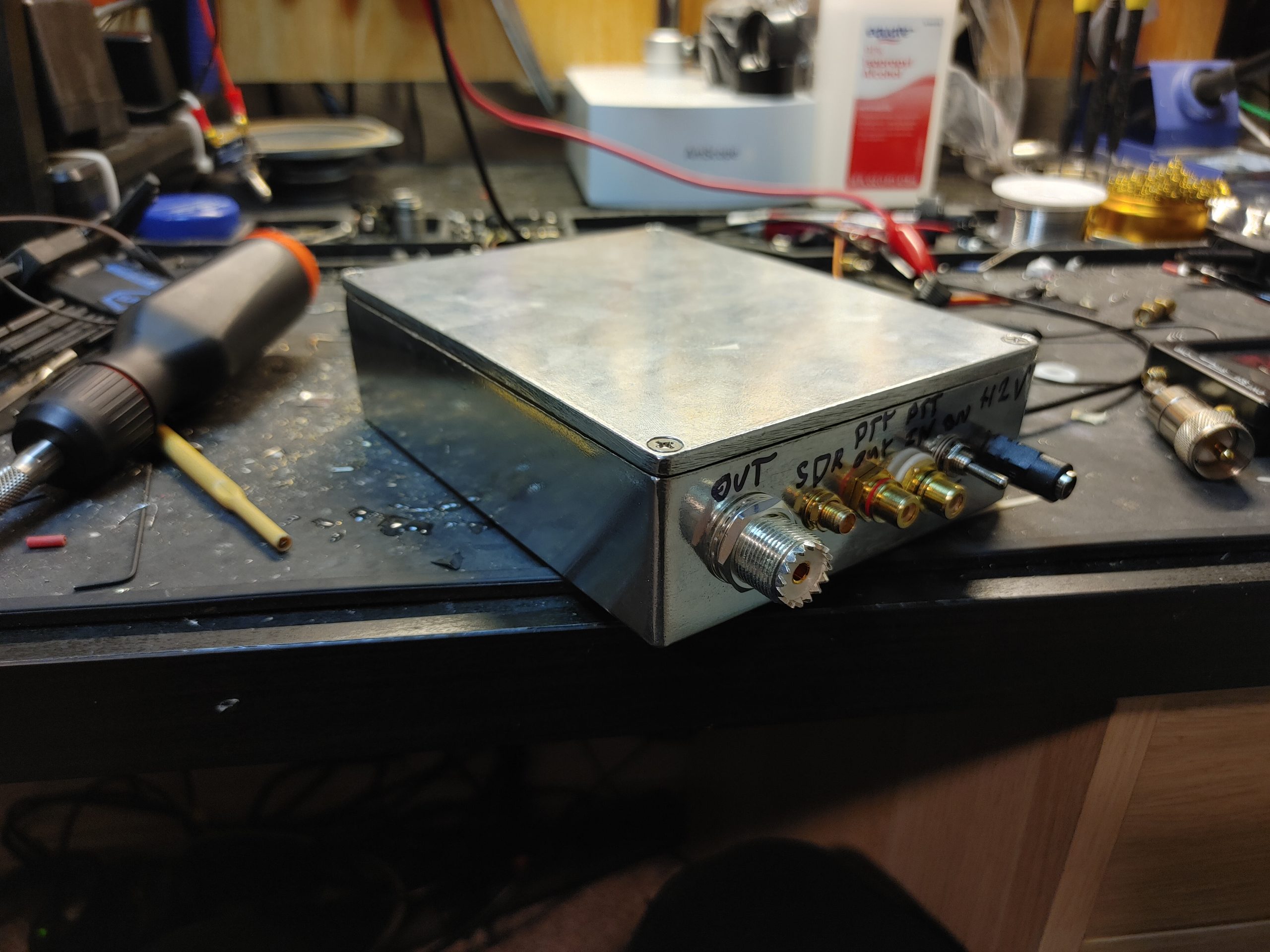
IO is as follows:
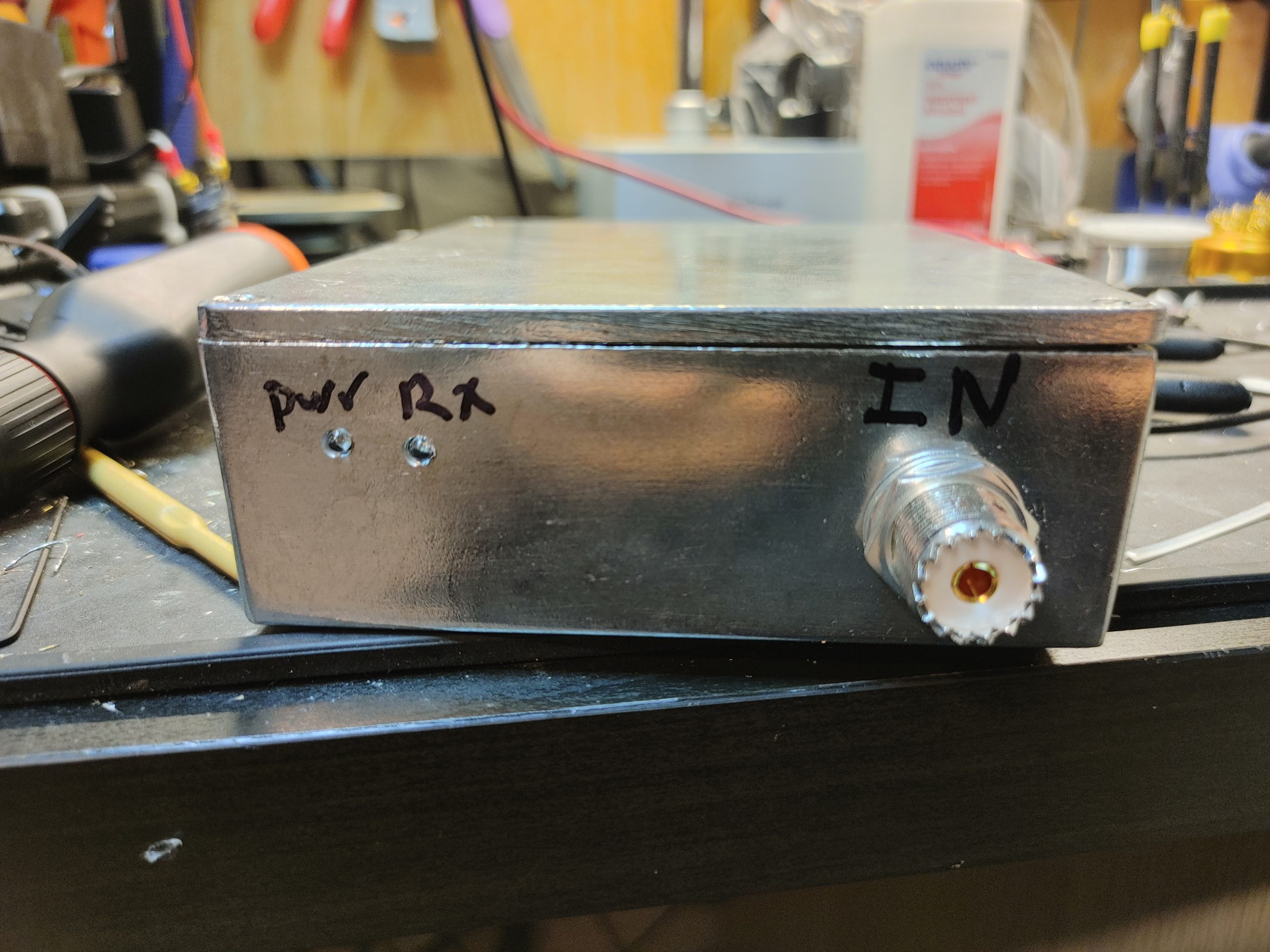
- SO-239 Input from antenna
- SO-239 output to transceivers
- SMA output to SDR
- RCA PTT input
- RCA PTT output
- +12V DC barrel connector
- Red RX indicator LED
- Green power indicator LED
- SPDT power switch (only SPST needed)
This is designed to have the default powered off behavior be pass-through so that no magic smoke incidents occur if you lose power or accidentally turn the box off. Thus, when the box is turned on, the relays kick on and the SDR port is connected. When the PTT is connected to ground, the relays turn off and the connection is straight through. I include a limiter ahead of the power divider to protect against the transients that may occur when keying up a radio and before the relays have time to switch over. I also added FM and AM notch filters to reduce distortion in the SDRs I use. I have some strong FM signals here that just love mixing and aliasing into my pass-band.
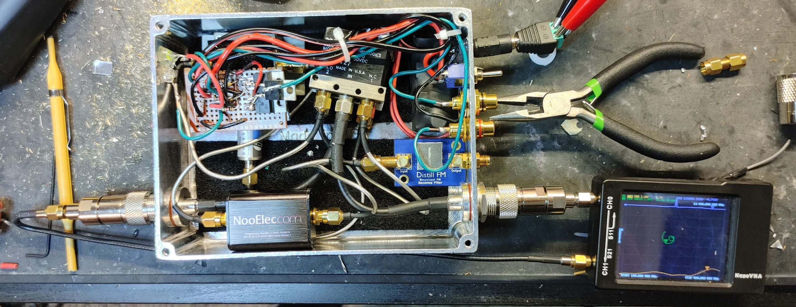
Performance is actually quite decent, with a maximum insertion loss of about -0.8dB at 450MHz on the TRX port. On the SDR port, this loss is just about -6dB which is the nominal loss of the power divider. This is excellent compared to that stupid MFJ box which uses a regular DPDT relay for it’s switching. Port isolation is also >=70dB when PTT is low. my nanoVNA is unable to measure past this. See the below images for a few of the measurements. Curves were a bit erratic because I forgot to terminate the unused port when I took these.
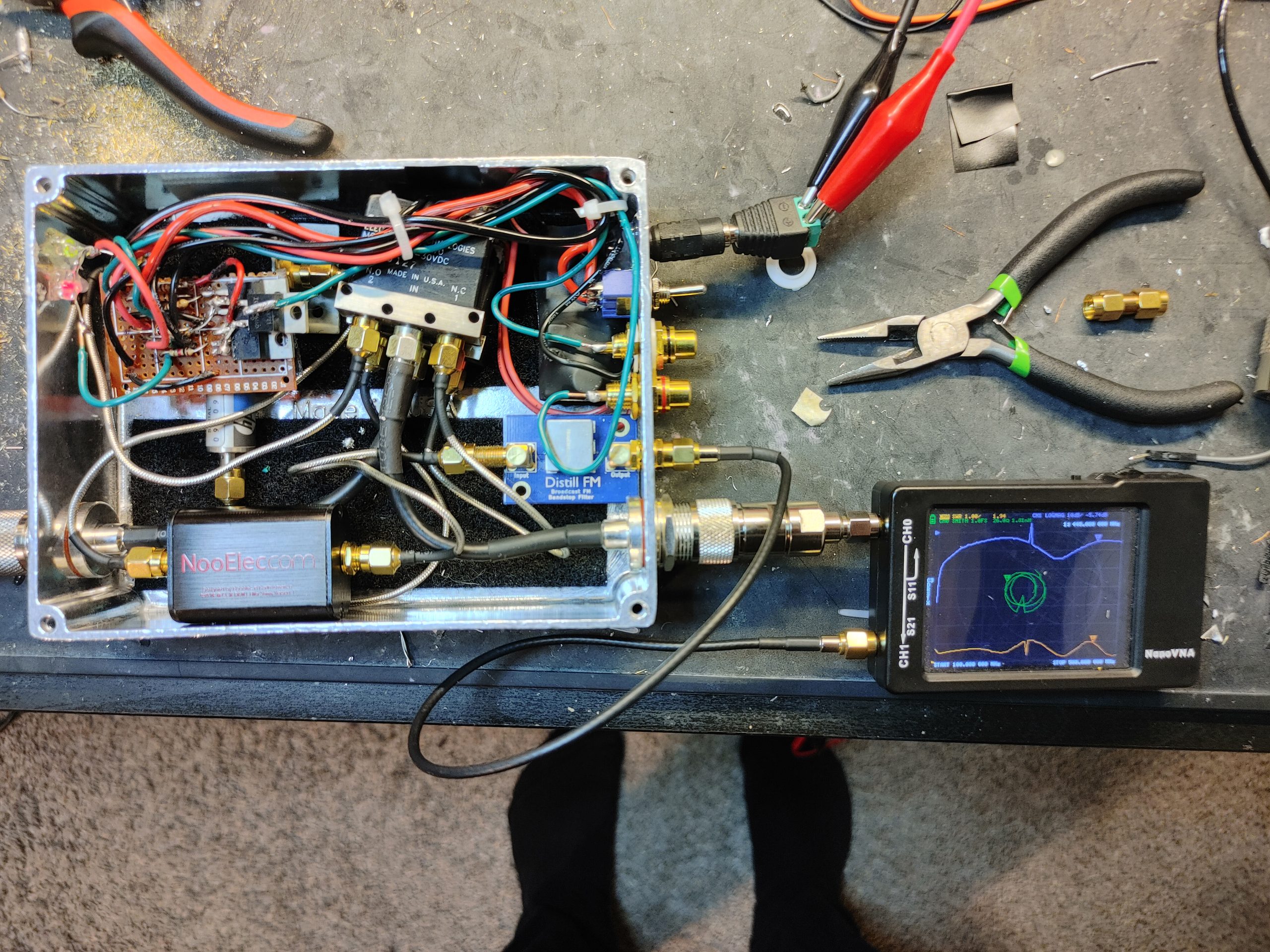
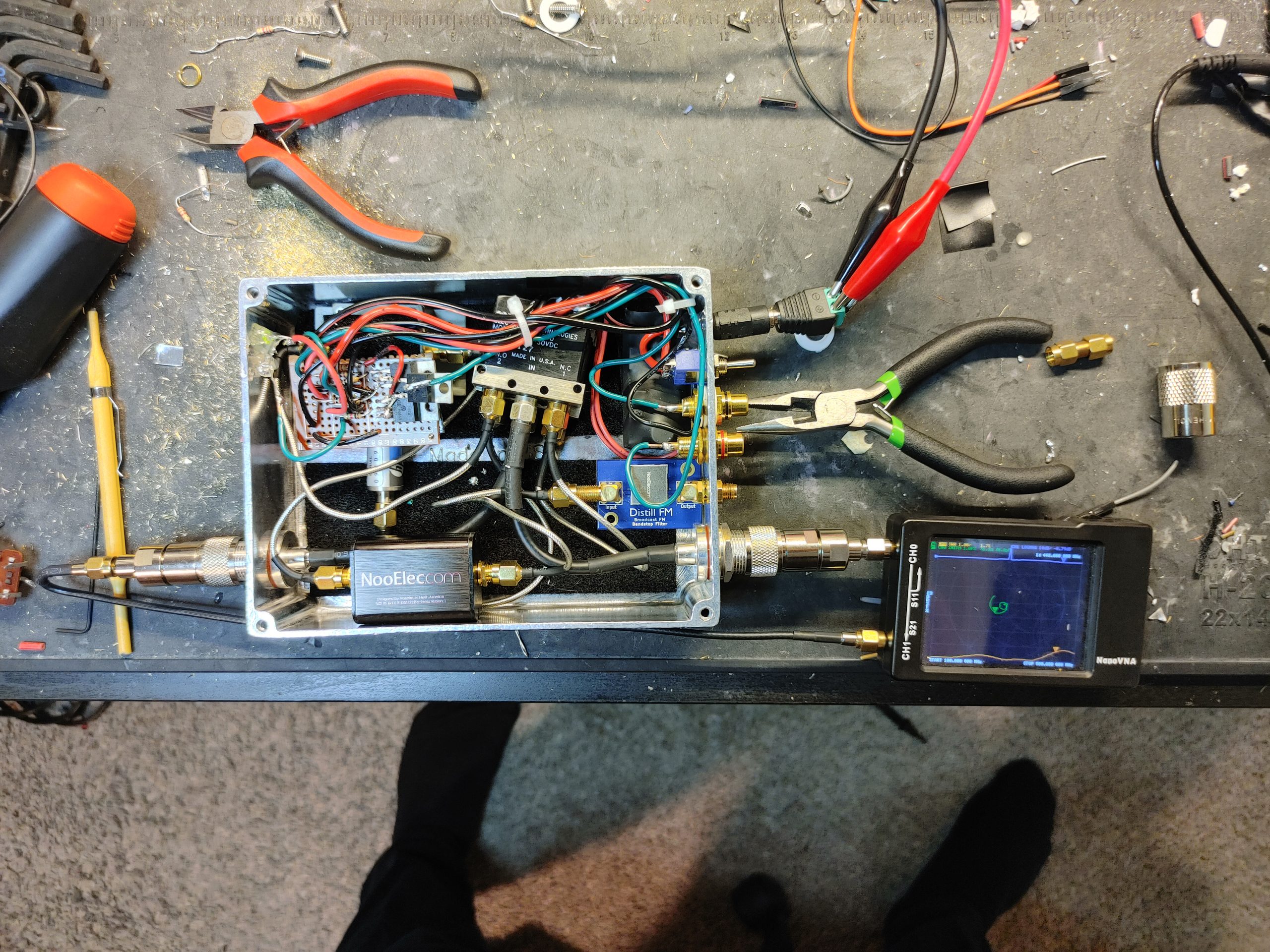
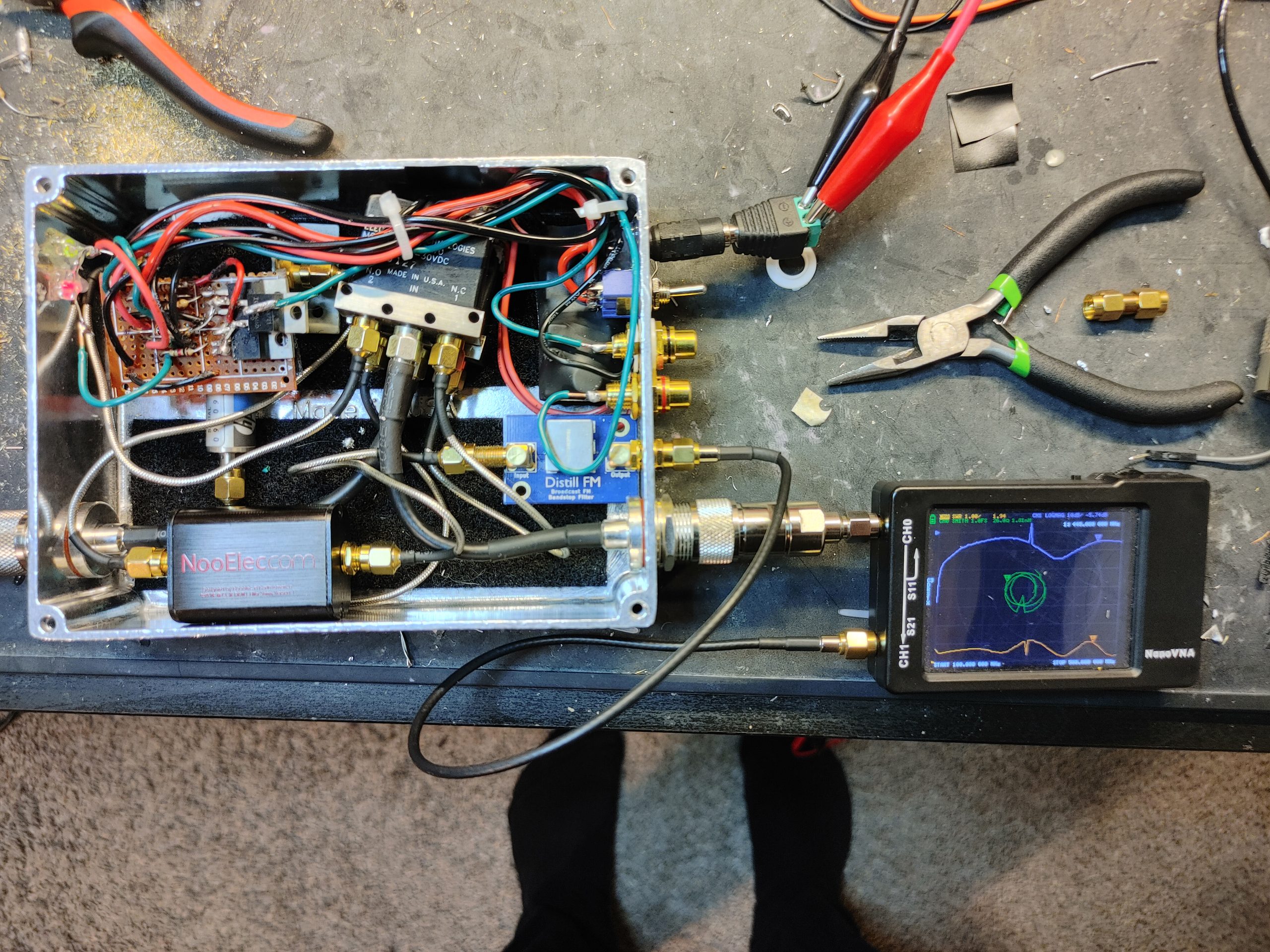

Here’s more shots of the box when all put together and installed


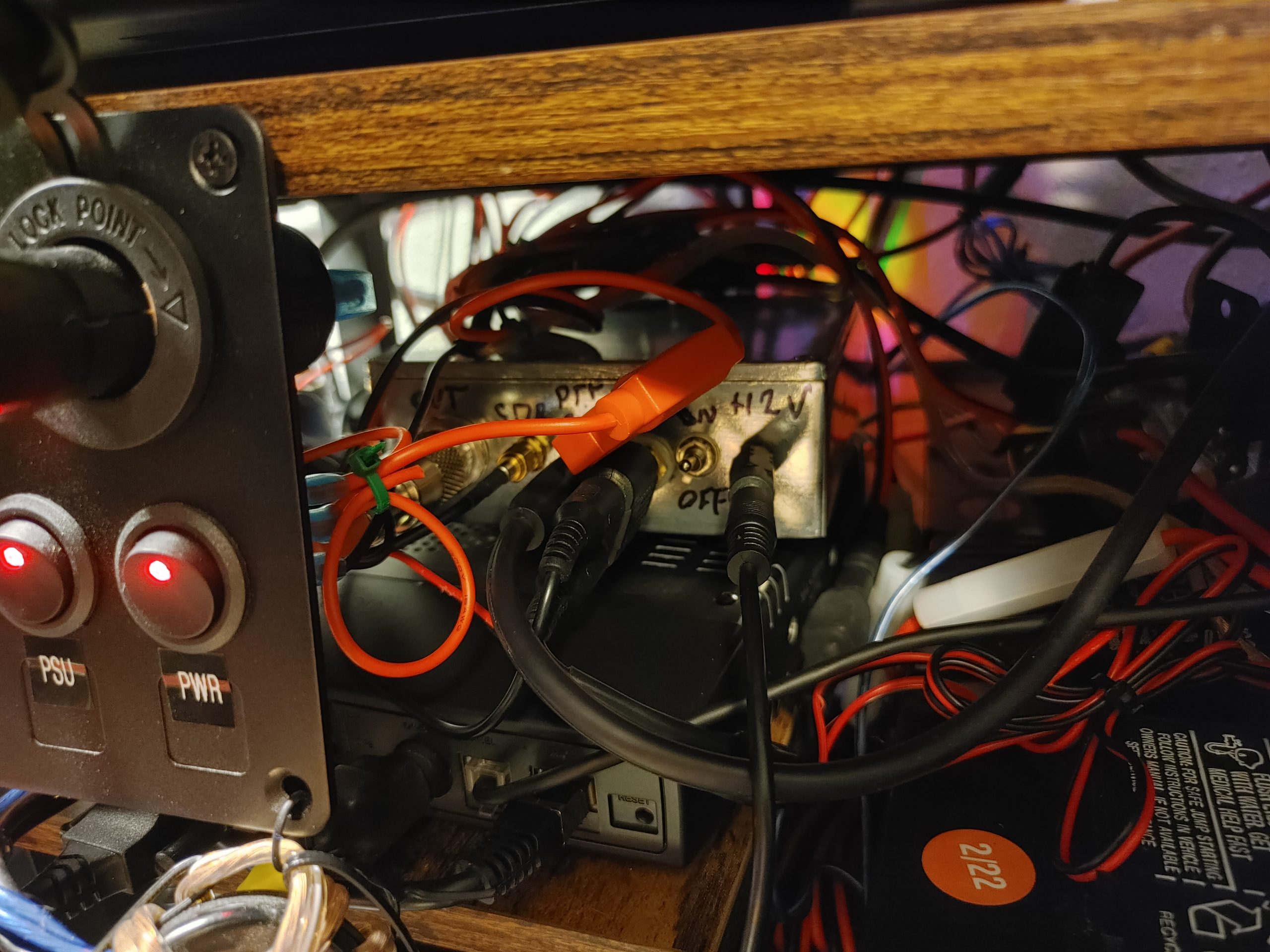
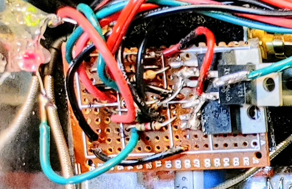
Overall I’m very happy. This was a massive improvement over what I had before. Some of the parts were definitely overkill, like the relays and MOSFETs used, but I’d much rather that than underrated components. One thing I did find annoying is that I had to use 3 transistors because I needed PTT output logic to be inverted. When I tried tapping the primary transistor for this signal I had all sorts of strange issues with voltages not being as expected, so I just gave up and made a logic inverter the “proper” way. The performance of this box is guaranteed to at least 100W of RF power and 1.8GHz. Though the SO-239 connectors actually limit the practical frequency at 600MHz or less. With SMA or N connectors this would easily work up to at least 1.8GHz with very low losses. This still works fine for me as 80% of the signals I care about are below 500MHz and 90% are below 1GHz anyway.
Here’s a slightly broken demo of the function. The needle nose pliers I was using to actuate the PTT slipped and caused it to key rapidly, but you can understand the general behavior.
And since you asked for it, here’s the prototype which this replaced. Shockingly the “thing” below actually lasted me almost 2 years, and I was only motivated to replace it because I’m pretty sure I wore out the relays (I operate a lot of VHF packet).
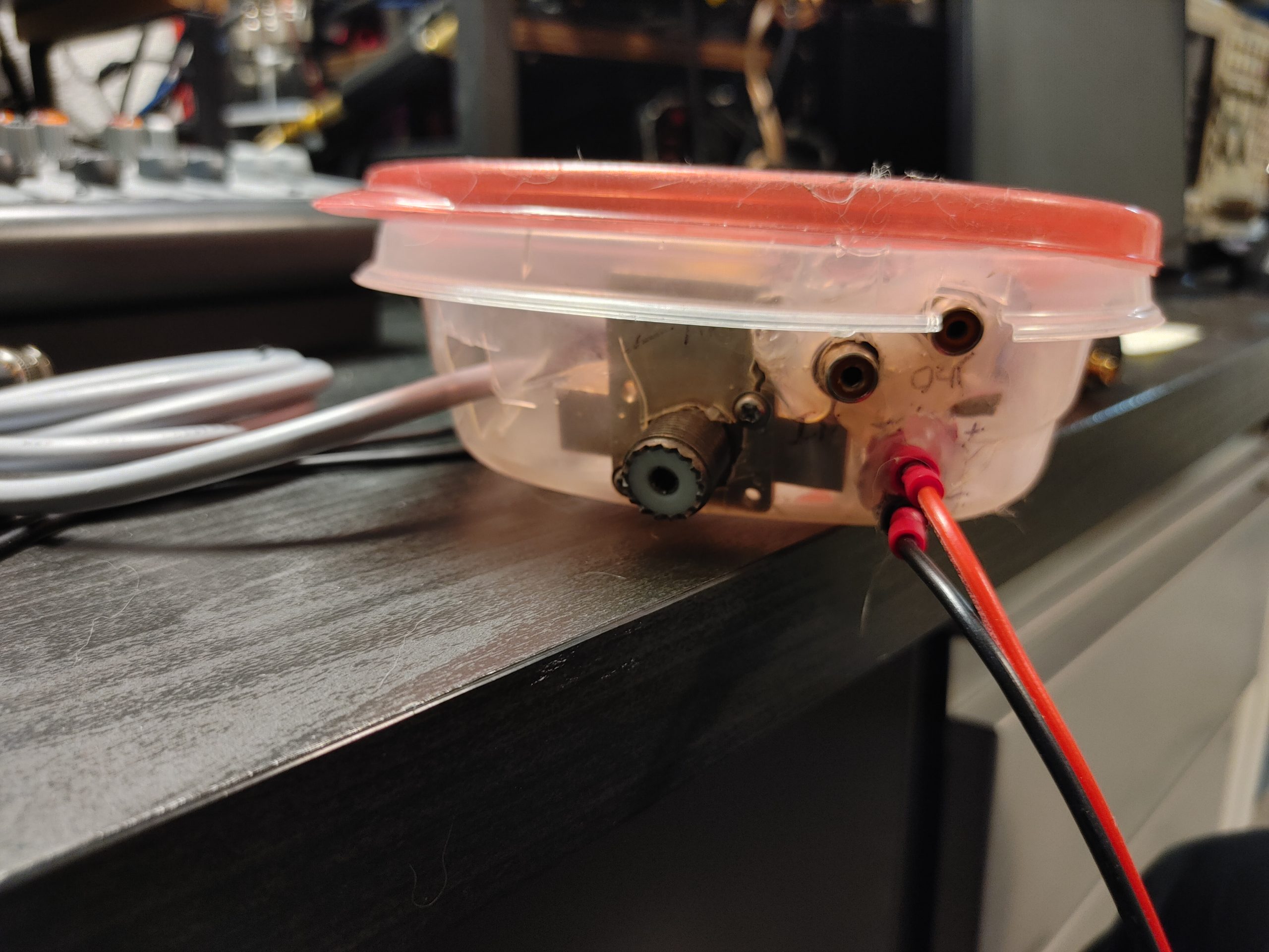

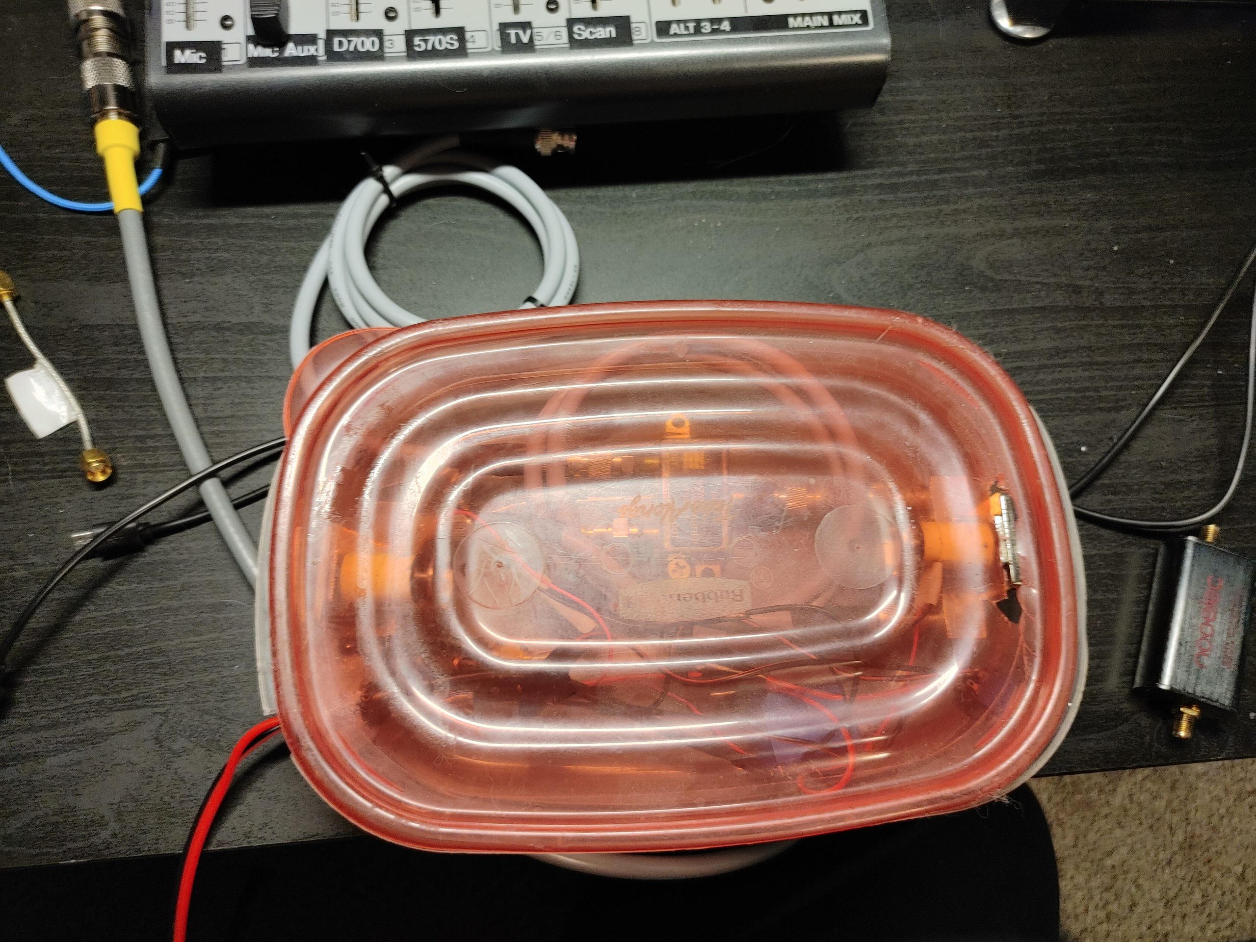
This thing was really thrown together to the point where I even poached the divider out of it and replaced it with an F-type coaxial power divider I literally found in my crawl space. It worked though!
Leave a Reply