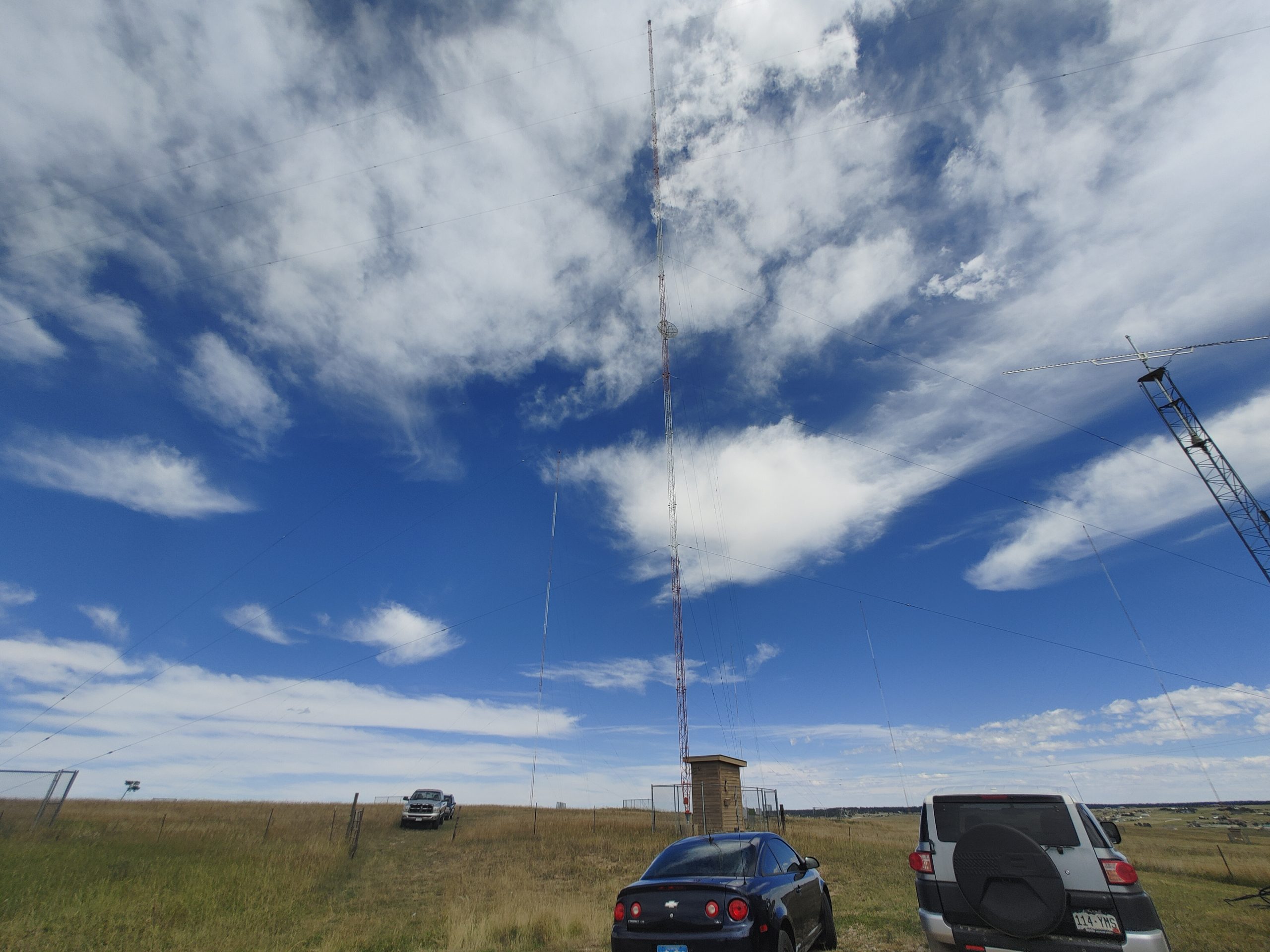
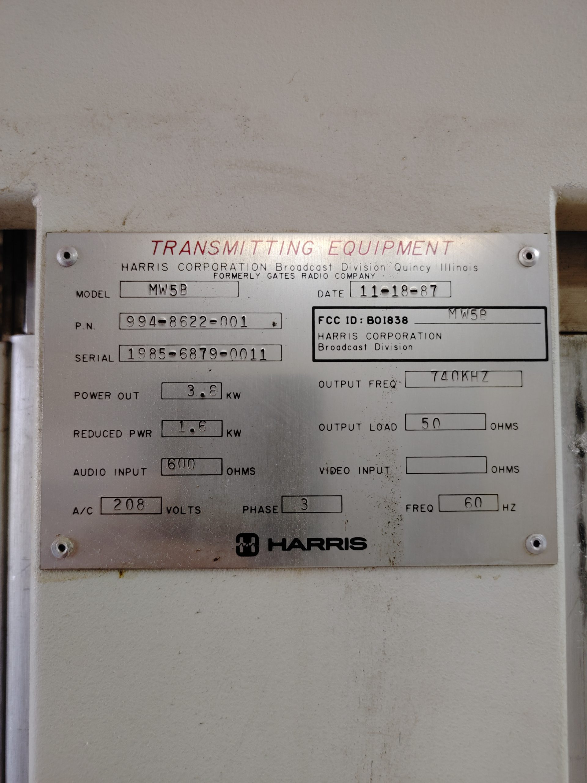
Ray Uberecken, broadcast engineer for the local Cumulus Media branch was kind enough to show me around the site for the KVOR AM transmitter located in Black Forest northeast of Colorado Springs, CO. This was a fascinating trip that taught me a lot about the trials and tribulations of running a true broadcast radio station. This particular station is relatively average in terms of power output at 3.6kW, but makes itself unique with the array of 6 antennas arranged in a vaguely trapezoidal pattern.

These masts are quarter wave ~330ft mono-pole antennas spaced at about 1/4 wavelength from each other.


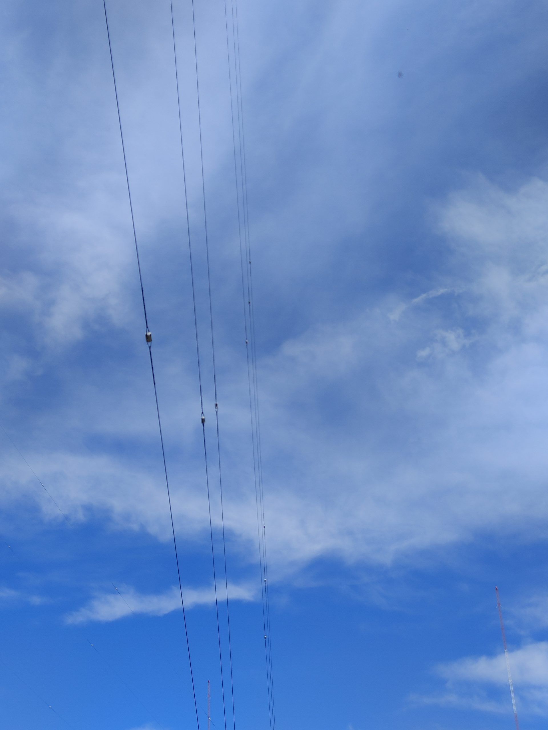
Note in the above images how you can see the guy wires are insulated multiple times throughout their length. This is because the entire tower structure here is energized and insulated at the base. The guy wires must hence be de-coupled from the antenna via multiple insulators to prevent them from being any resonant or significant fraction of the wavelength that would unintentionally electrically load the antenna.
Subsequently, this also means that a good ground system is required since these are resonant mono-pole antennas. Pretty much the entirety of this property is covered with an interconnected radial system. There are supposedly something on the order of 100 radials per antenna which are soldered together underground where they meet.

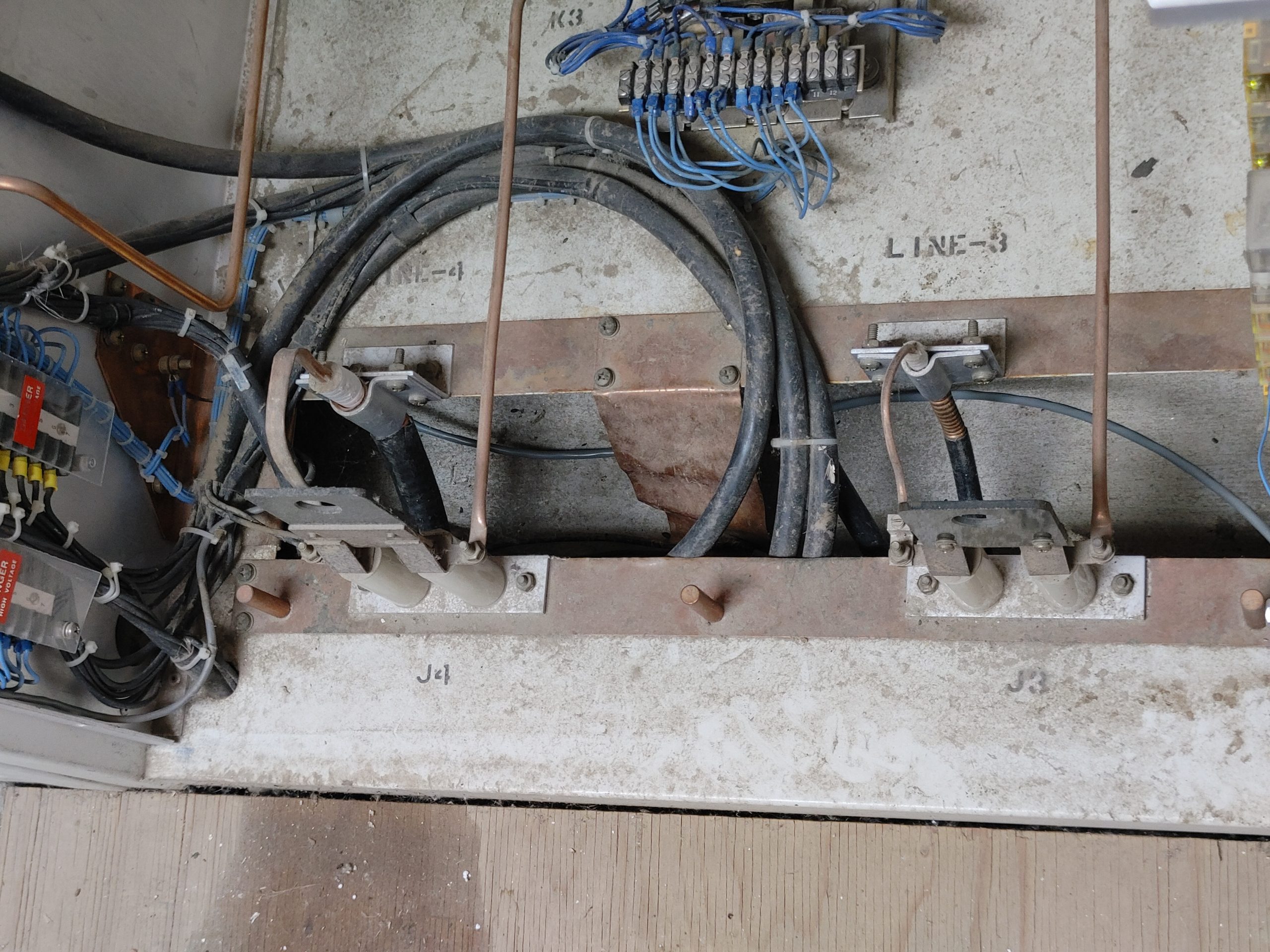
Here’s the base of the antenna where you can see the insulator, grounding, lightning protection and feeder.

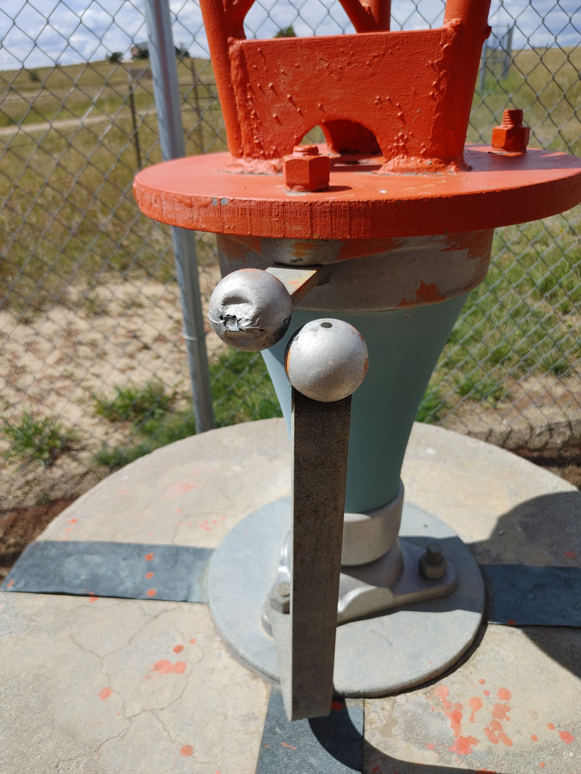

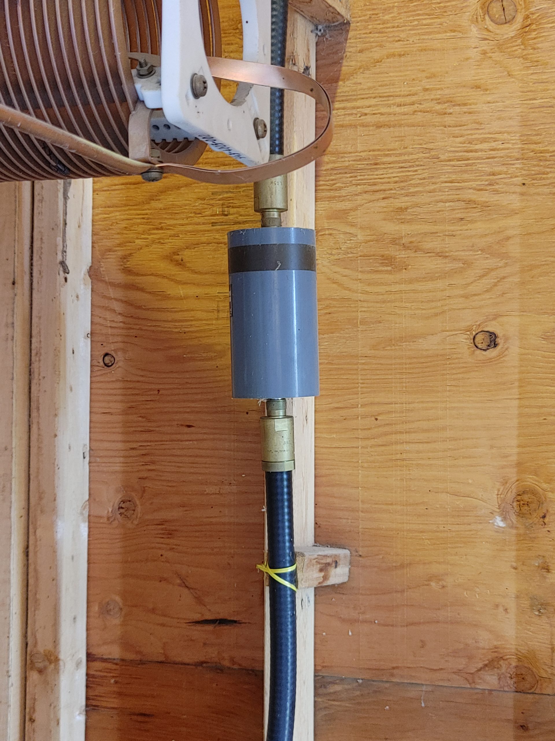
These three images are fascinating to me, and show a lot of the unique design techniques used. Firstly, there’s the feeder which you can see is a black rod sloping at an angle down to a bracket on the tower. This is how the antenna is fed. At the shack you see two large coils which are used to choke the initial pulse of lightning strikes. Snaked through this coil is the feeder for a microwave studio-transmitter-link (STL) antenna. Next, you see the second line of lightning defense. These balls are set a specific distance apart to allow high enough voltages from lightning strikes to ionize the gap and shunt to ground to reduce damage to electrical equipment inside. Lastly, you see the grounding straps that connect the base of the tower to the ground system. Note that the whole thing sits on a large blue insulator so the red and grey metal parts are electrically separated to allow signal potential to form across the gap.
What’s more is these antennas are individually tuned at the base by manually adjusted co-located tuning circuits located in small shacks. This is because due to variations in height, soil conditions, and various other physical factors, impedance is not purely real. These antennas should ideally be something like 36+j0 ohms, but are more like (15-25) +- j(0-15)ohms. This necessitates tuning for optimum power transfer.


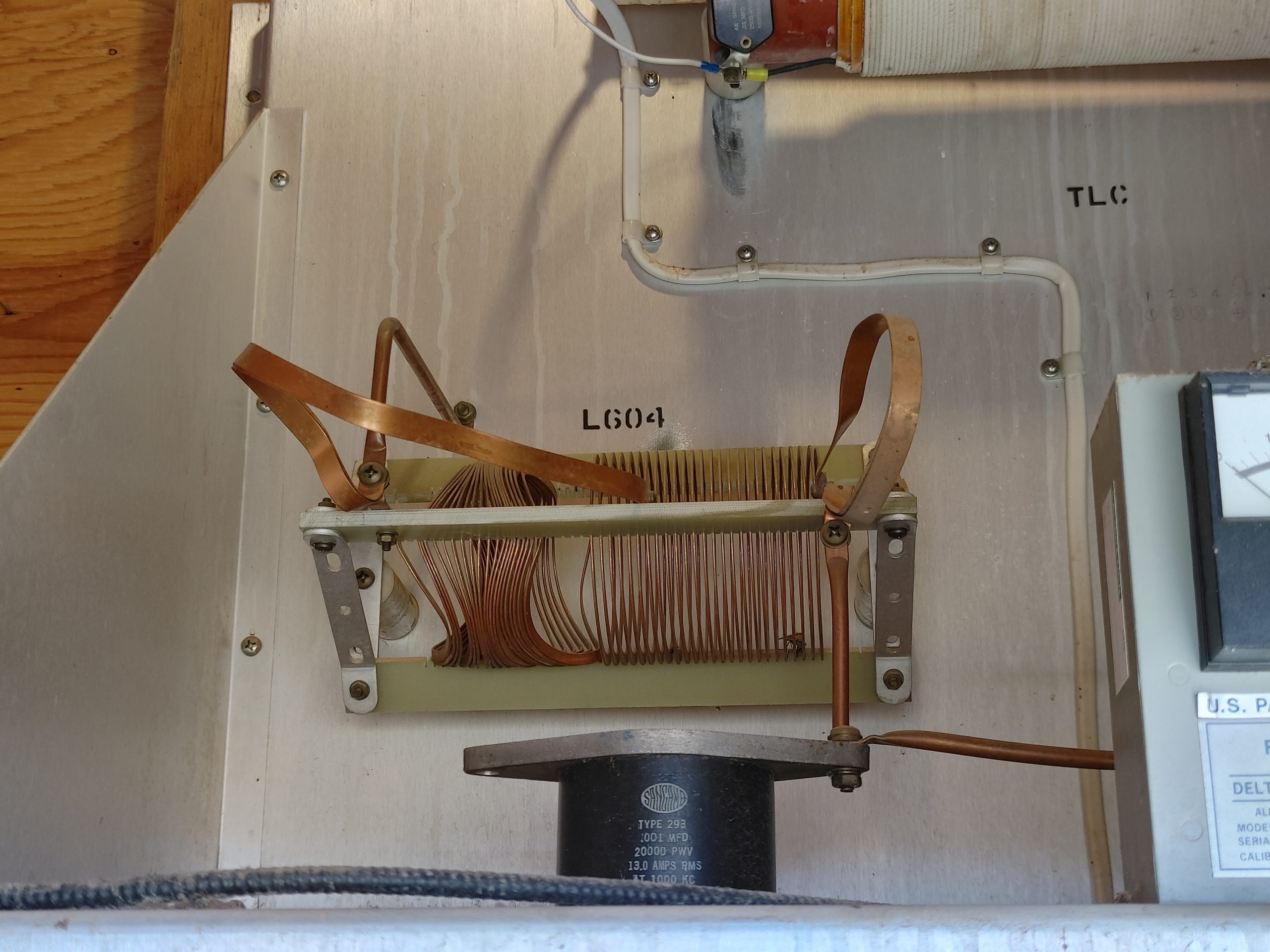


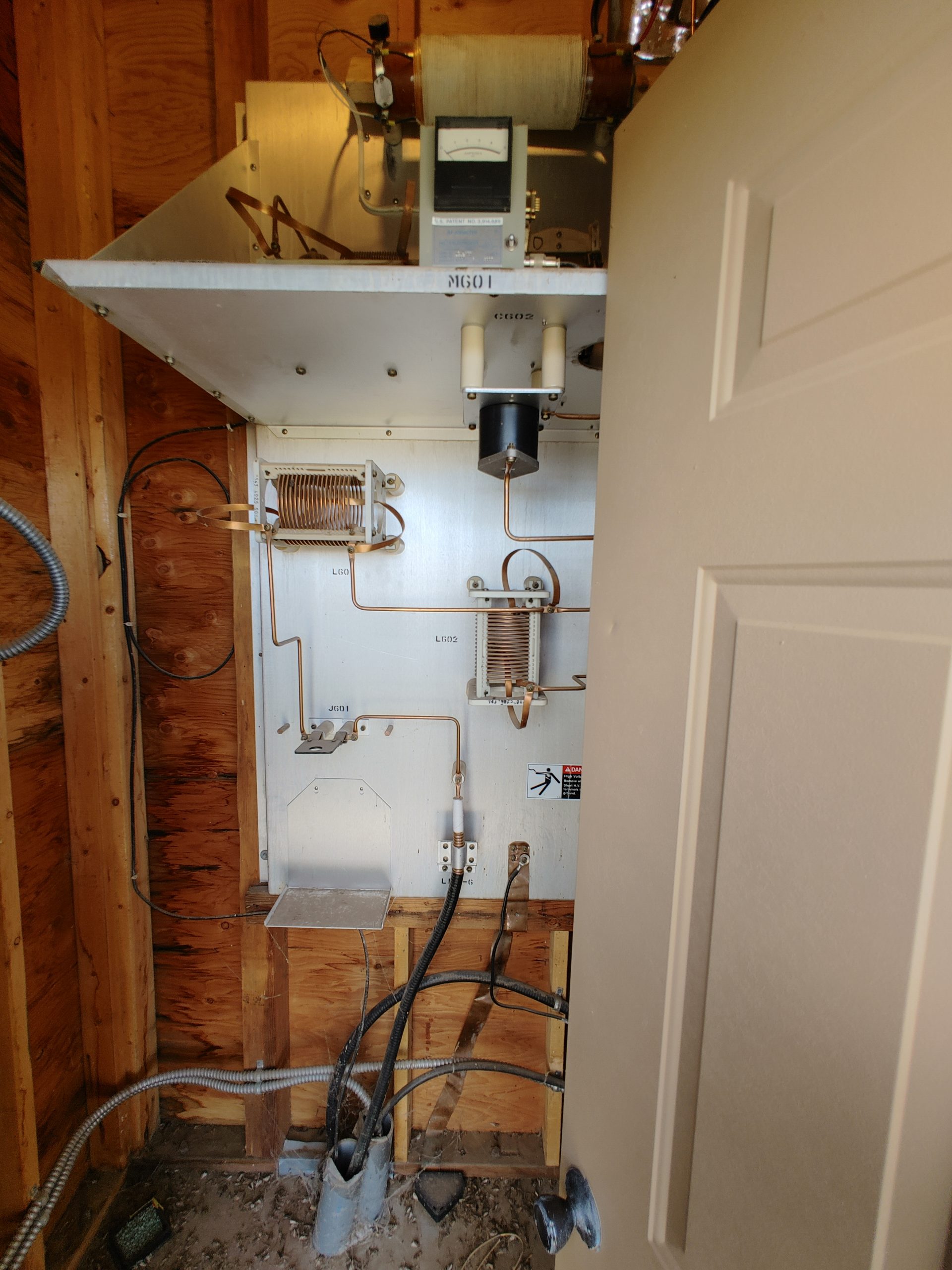
Another neat little Easter egg is the fact that you can hear the audio from this transmitter in various places on the site. Including seemingly emanating from one of the tuning coils. this is VERY quiet, you’ll need to max out your volume, but you can hear a strange raspy whining that corresponds to the current programming.
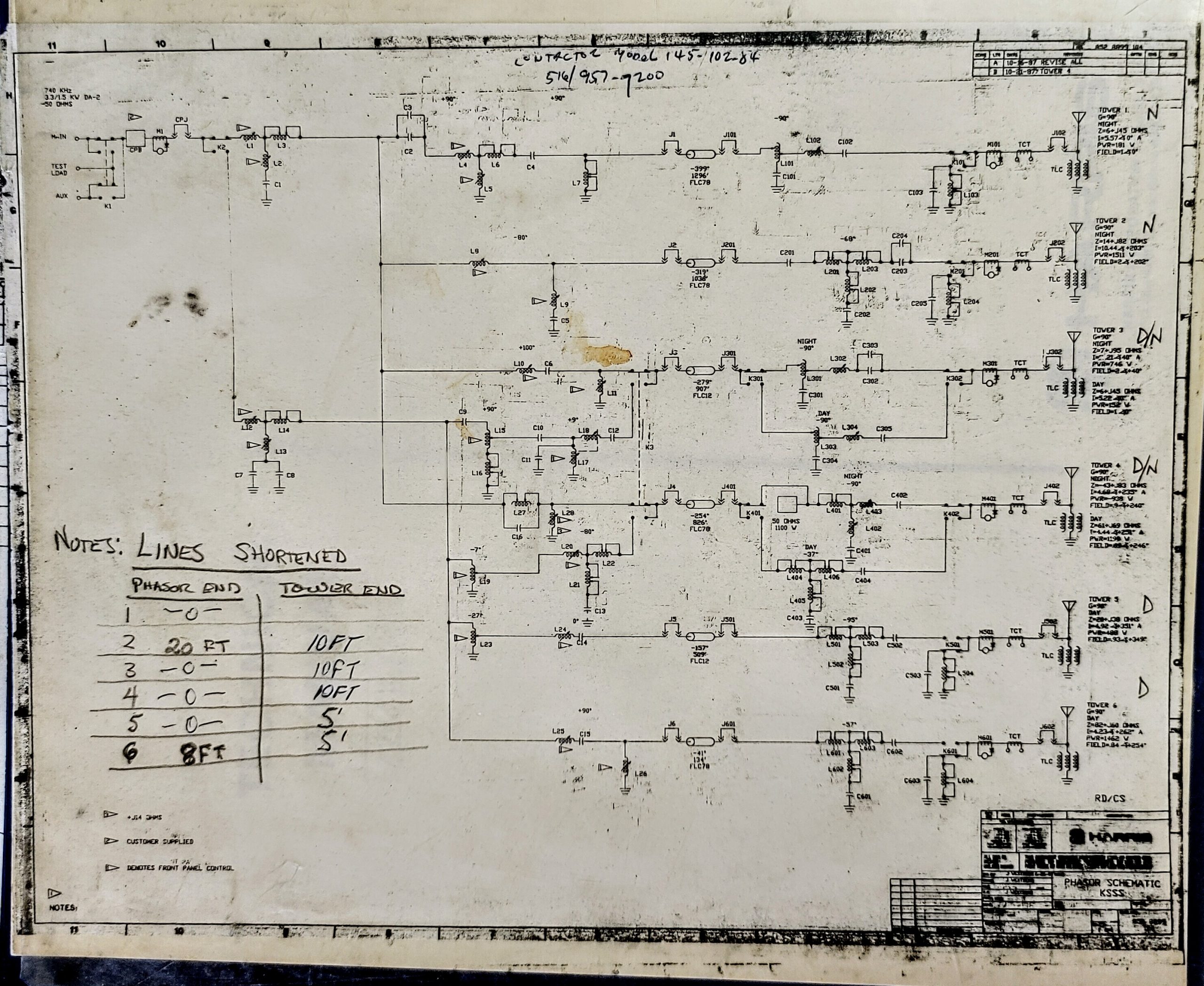
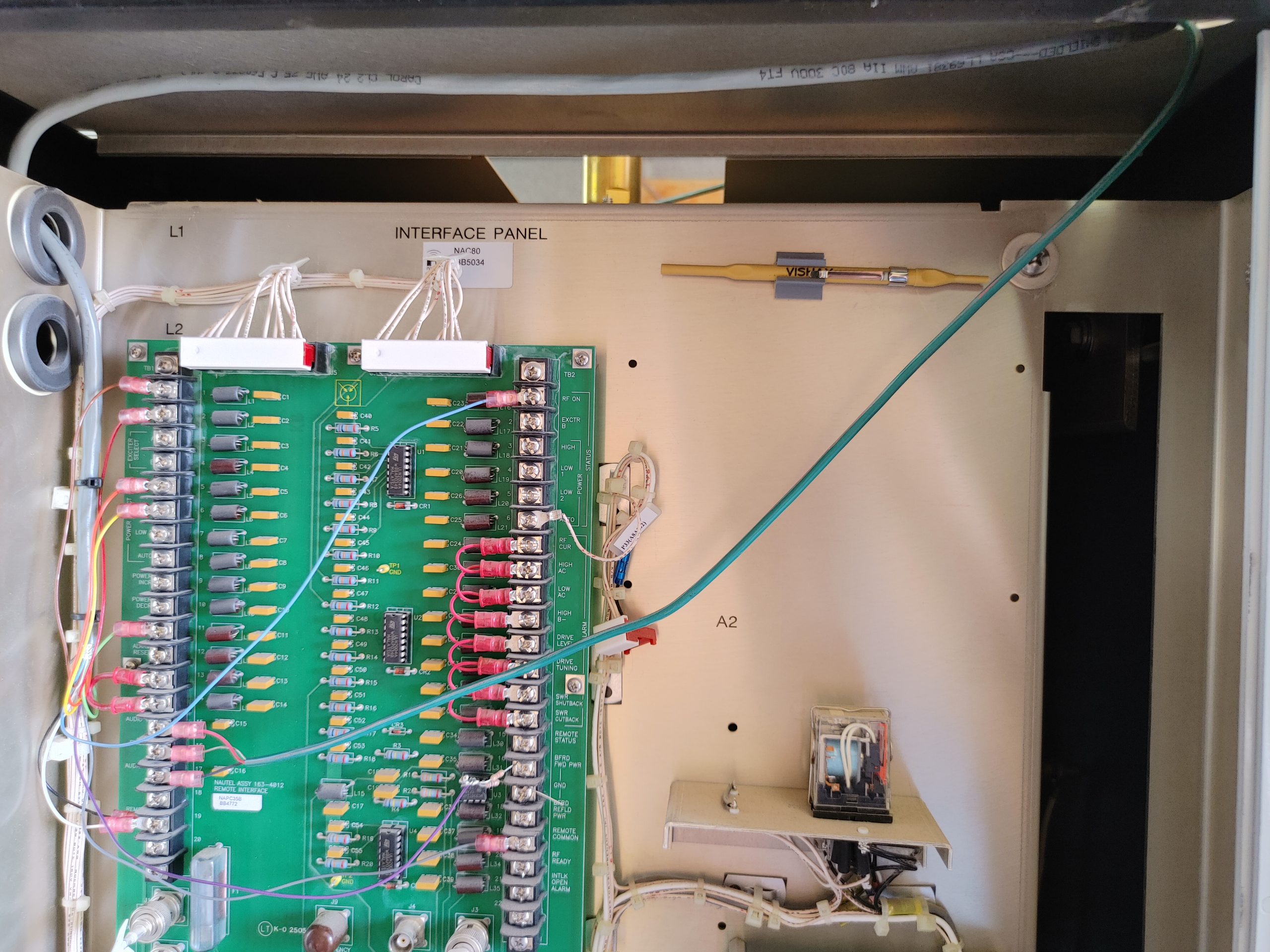
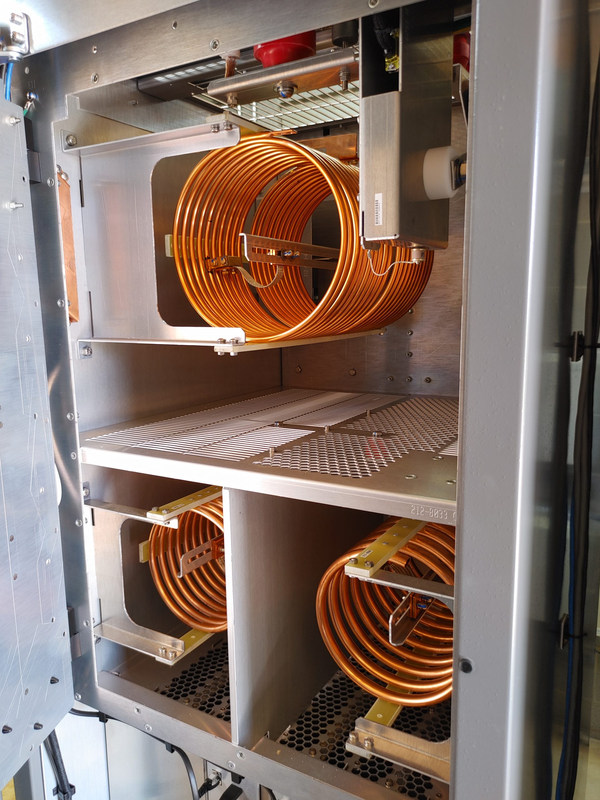
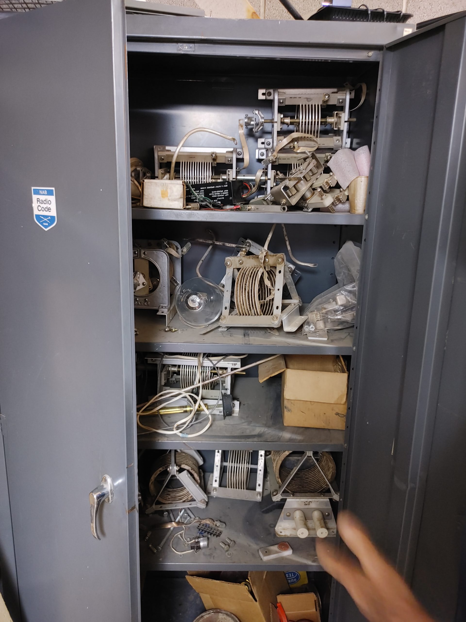
Once the antenna is matched to 50 ohms, it is sent down a 3/4″ rigid Heliax feedline back to the main shack where it hits a set of phase & amplitude adjusting combiners. These combiners are used to adjust the power and phase to each antenna, tuning the radiation pattern i.e. where the nulls and lobes get fired out.
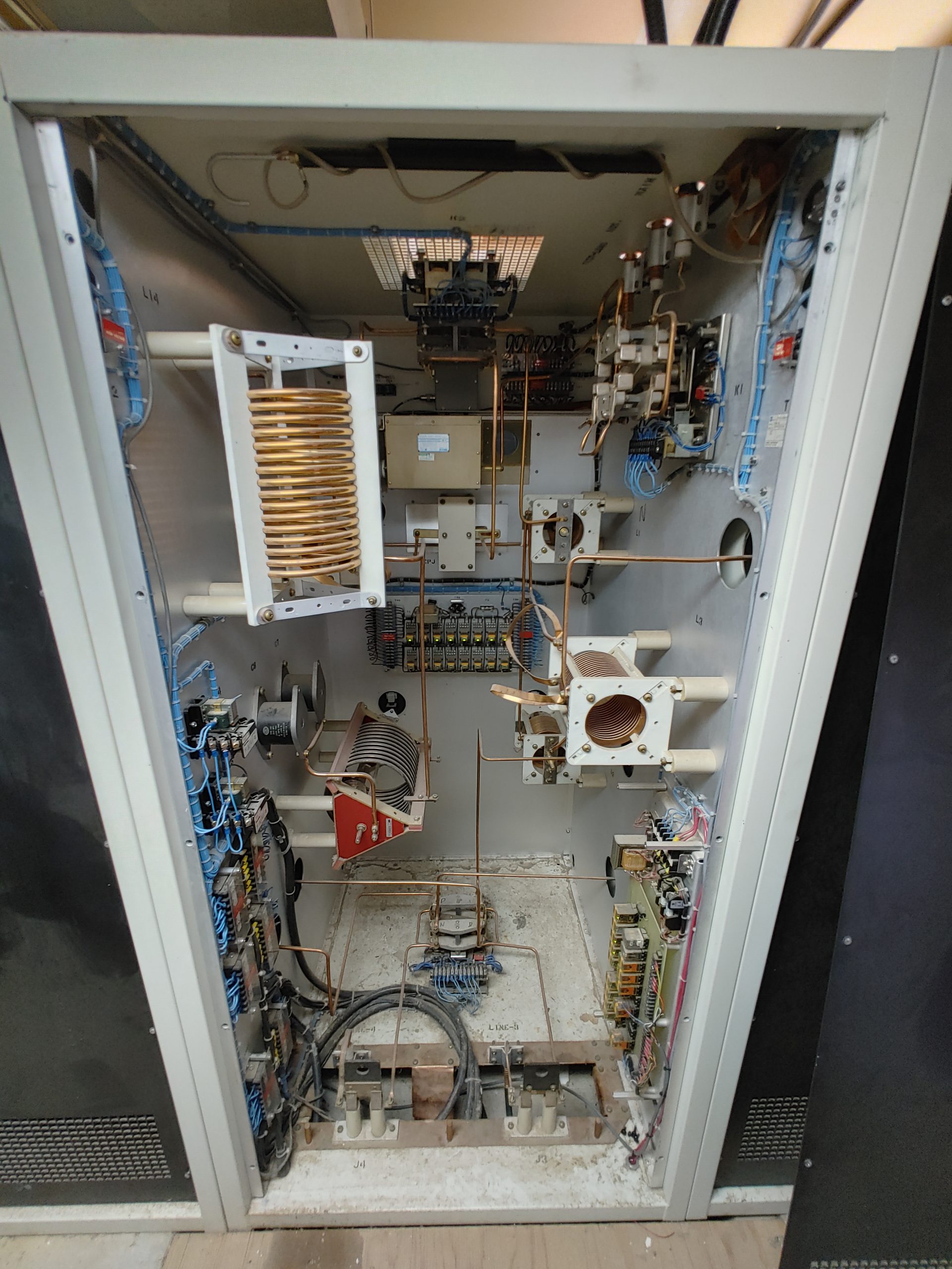
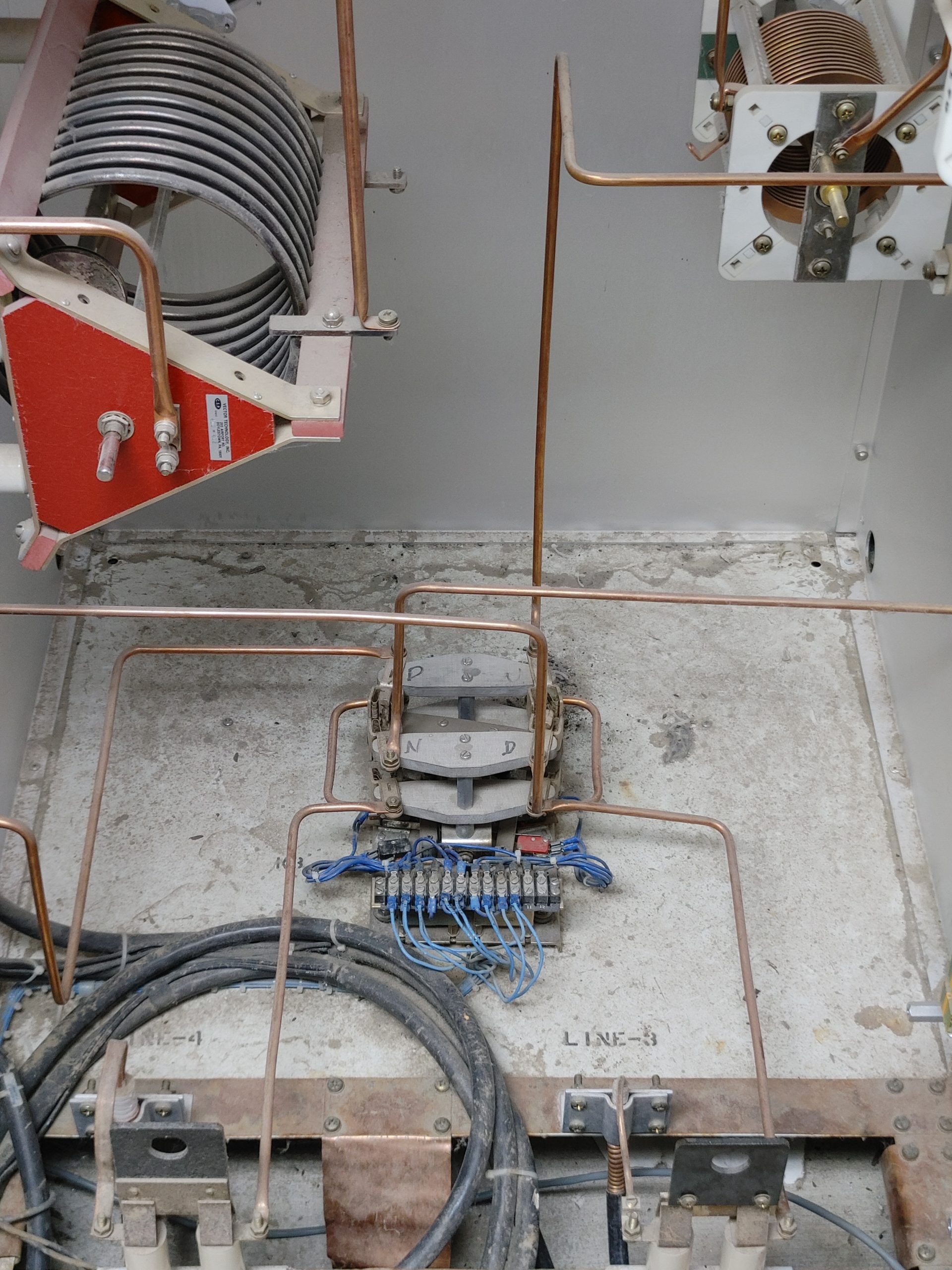


Another neat little tidbit about this combiner is the way that it does variable capacitance. Rather than using an expensive and fragile vacuum sealed variable capacitor, there is a roller inductor placed in series with two capacitors that is used to buck the capacitance to the desired amount. You can see this in the closeup shot in the middle left of the cabinet.
The interesting thing about this antenna configuration is that only 4 antennas are powered at a time. This is because they are used to change the radiation pattern between the day and night time in order to prevent interference to another nearby station on 740kc. This also explains the antenna spacing since this is not a gain oriented pattern. If that were the case, the elements would likely be linearly arranged with a 1/2 wavelength spacing rather than close to 1/4 as they are. The main daytime lobe is steered toward COS. At night the antennas are switched to throw a null in the direction of the other transmitter and power is reduced to 1.5kW.
This power reduction is standard in the AM broadcast industry since propagation opens up vastly at night with the reduction of the ionospheric D layer. This layer is highly absorbent to MW signals, it’s absence allowing much greater distance to be covered via refraction “skip” off the ionosphere. This station has apparently had reports come in all the way from Sweden!
Okay, now that we’re done geeking about the antenna and radiation system, let’s finally go take a look at some of the actual transmitter equipment.
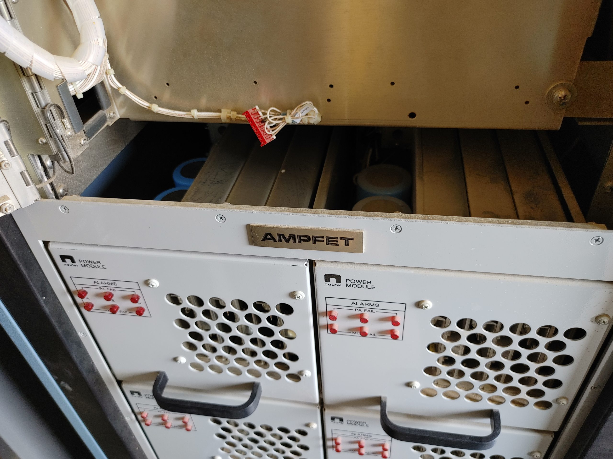
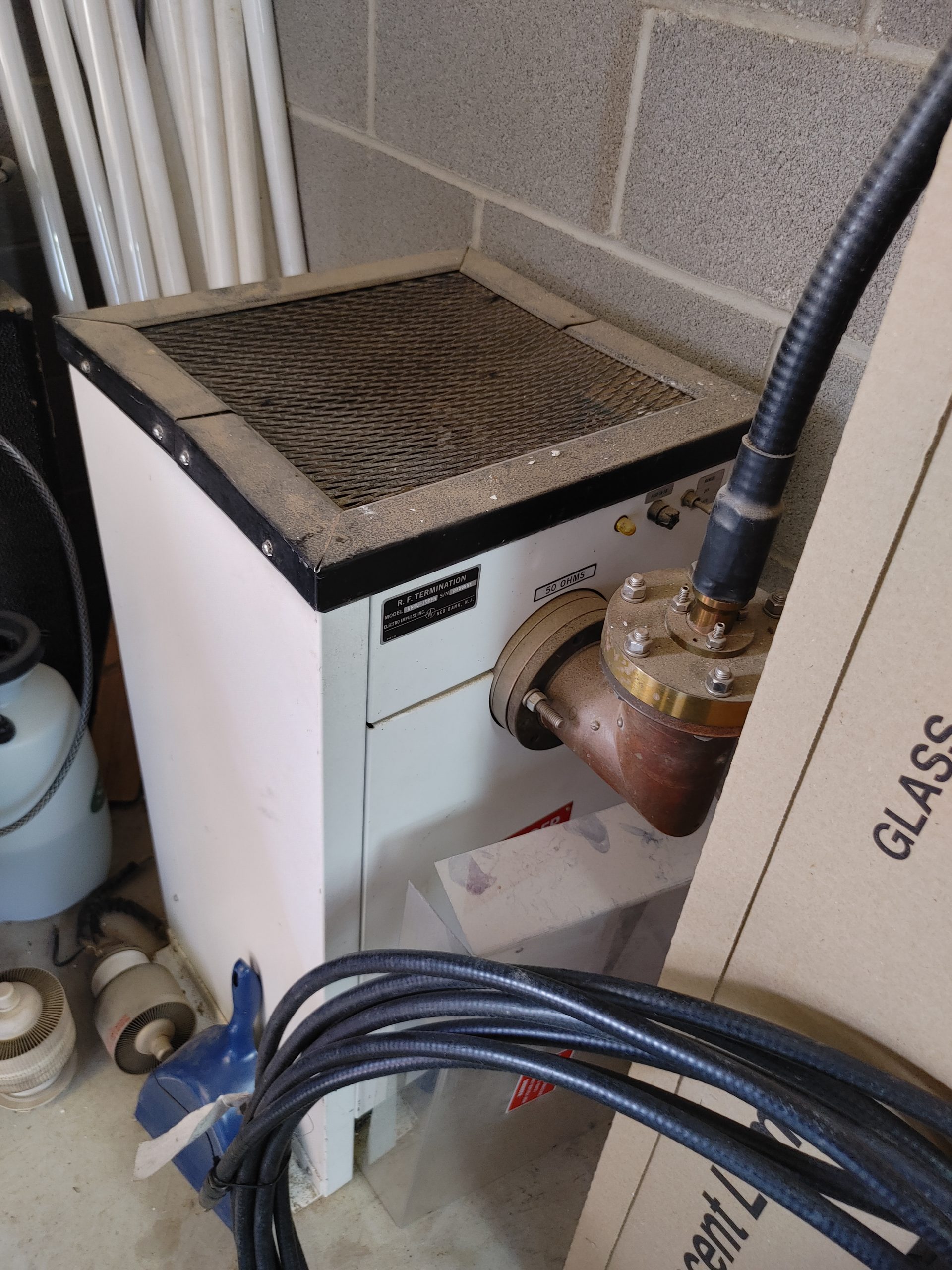
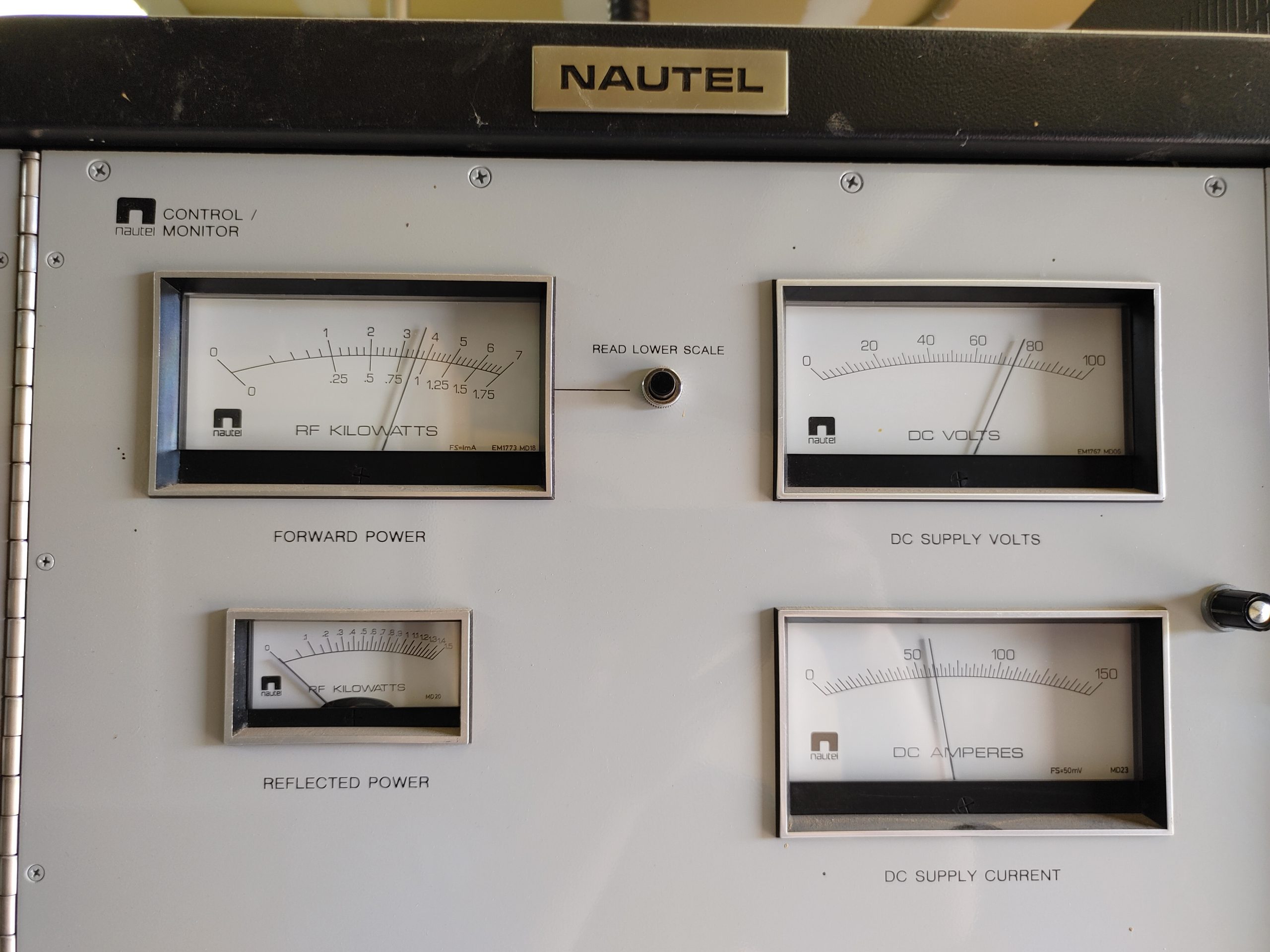

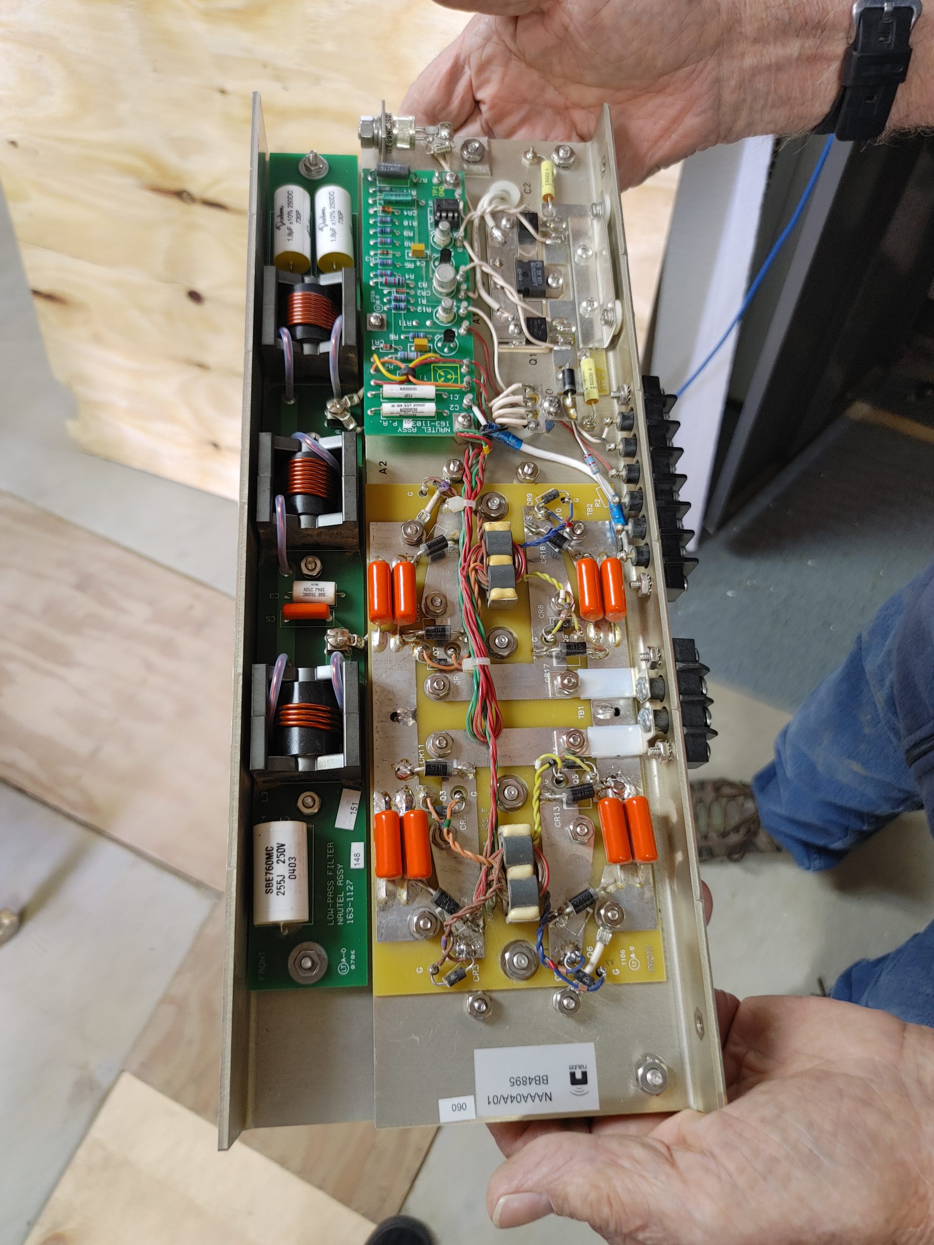
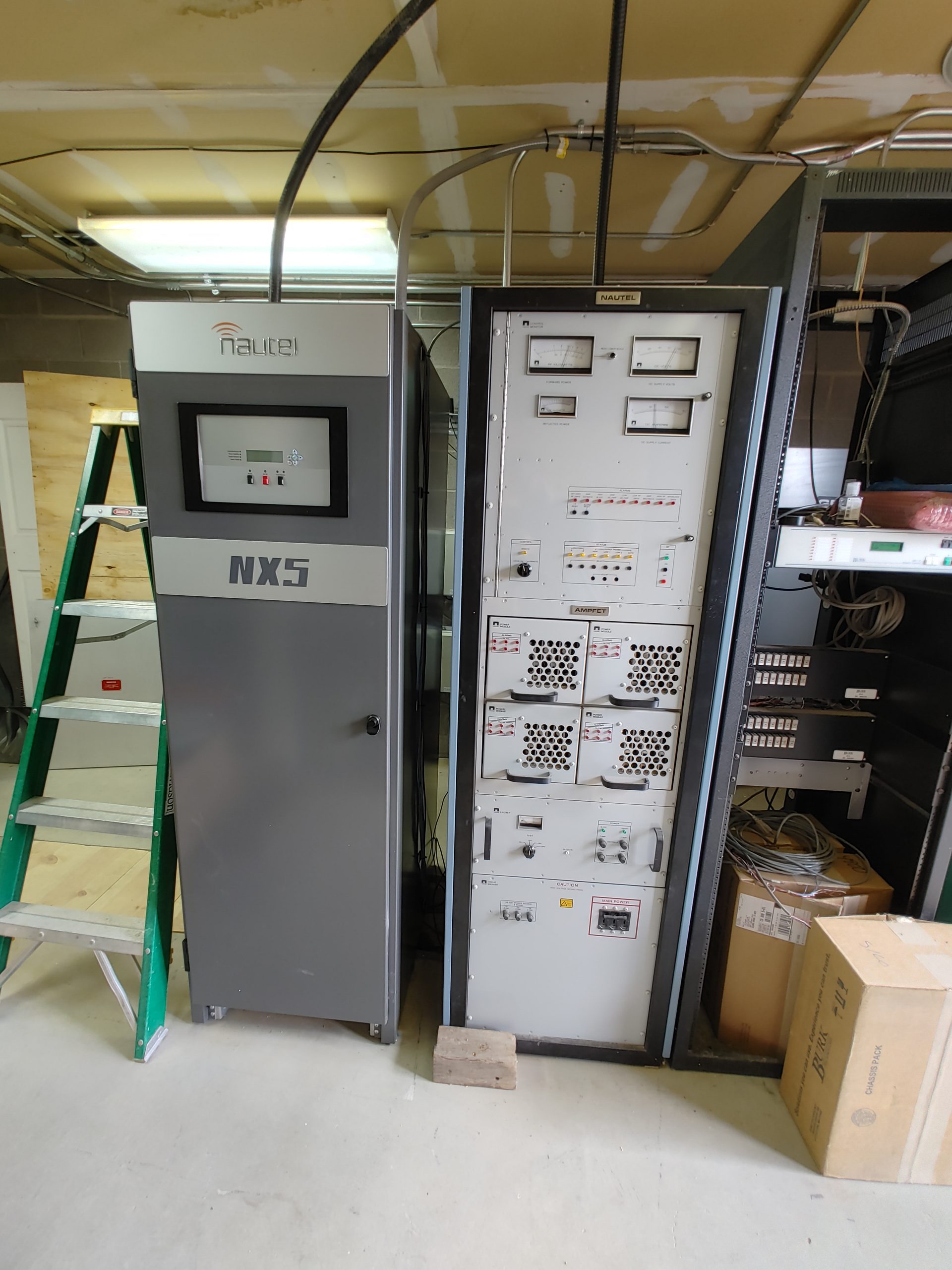
The above images show the primary transmitters used which are both rated 5kW. These are both solid state and linked together such that the failure of one can be tolerated by switching to the backup. This is another spot where you could hear some vibration corresponding to the transmitted audio. pretty cool. These power amplifiers are made up of 4 modules which are each capable of about 1.5kW. Each of these modules are themselves comprised of 3 cards which hold a number of transistors, all in parallel. I’m personally a really big fan of the quick release fine alignment tool stowed behind the front panel, just in case you have to make an emergency potentiometer adjustment. Also that has to be the biggest 50ohm load I’ve seen in my life.
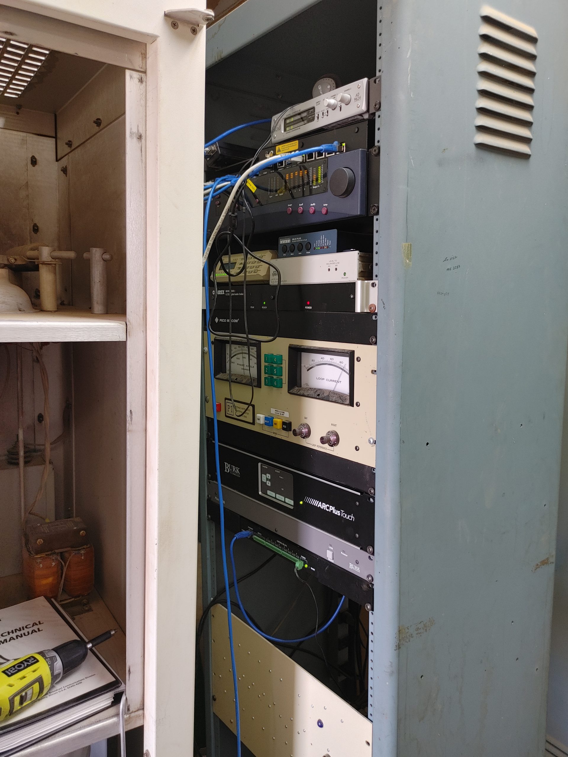
Here’s some of the audio and STL equipment. This is interesting because there are multiple paths for the audio to make it to the transmitter. Currently they have 1/24th of a T1 line at 56k as their primary audio source. They then have a silence detector that can automatically switch them to a microwave internet link in case they have a “Backhoe Fade”. If you’re not familiar with this channel, that’s because unfortunately most signals textbooks forget to include this alongside the likes of the Rician and Rayleigh fading models. This is a unique kind of fading that occurs when a backhoe accidentally cuts through their telephone line and causes a prolonged silence, i.e. fade. They also used to have a 900MHz analog STL link which is still up on the 1st tower, though this is unused.

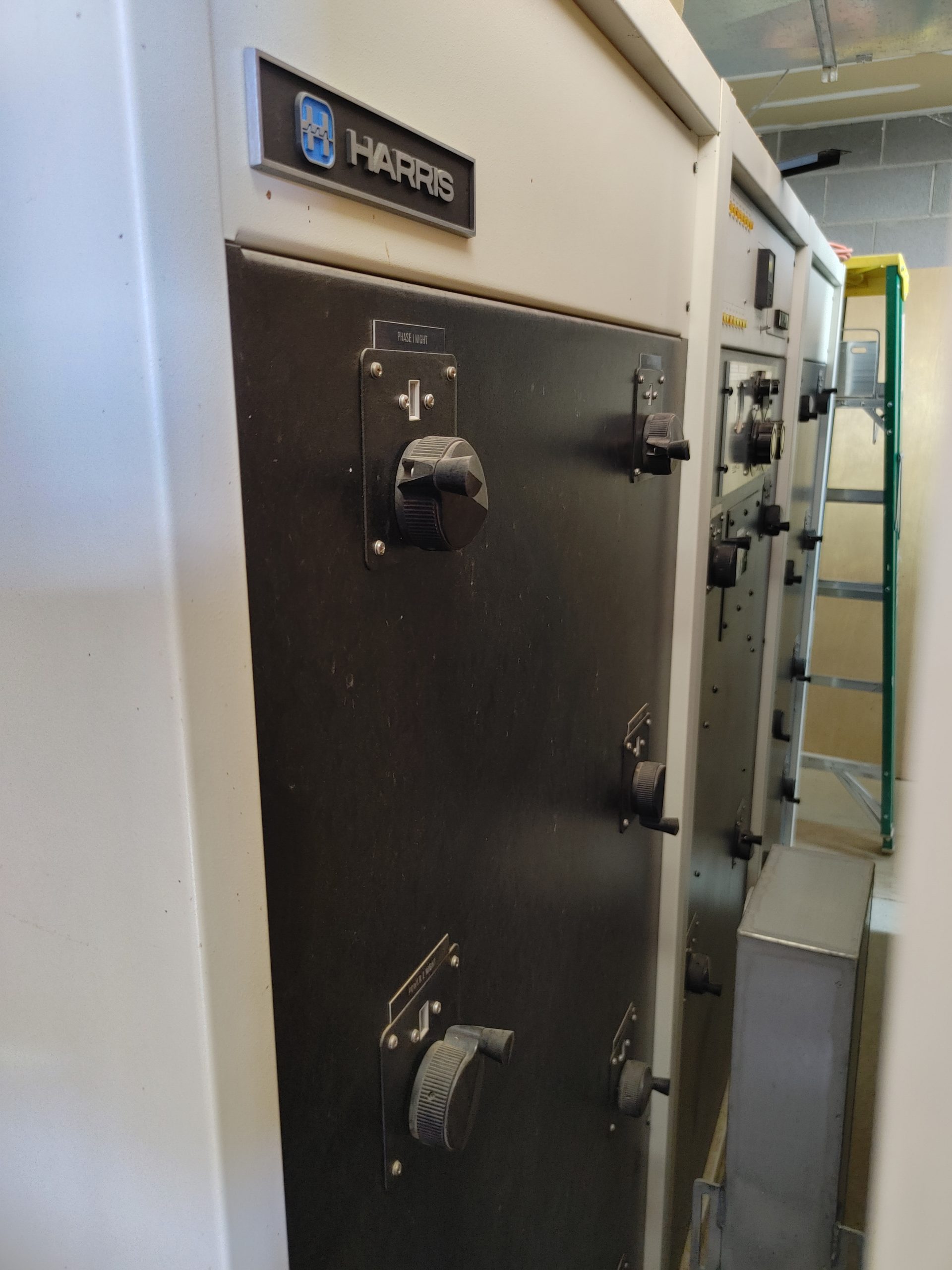
So there’s one more thing of interest in here, and that’s the old vacuum tube based power amplifier. This hulking 1200lb beast was the original transmitter until it was replaced by the solid state units sometime in the early 2000’s.

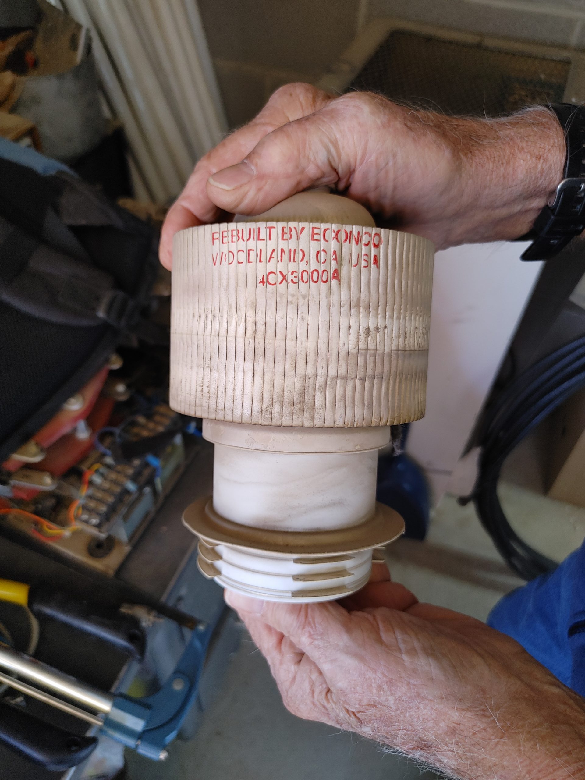

This particular unit houses many interesting and amusing secrets. This is essentially a two device class C amplifier capable of producing about 5kW. This thing has a plate voltage of about 13kV and requires 3-phase 208V power. Above you may have seen Ray holding the “Jesus stick”, this is one of two devices located on the inside of both removed door panels. This stick is attached to an interlock mechanism that will not allow the transmitter to be powered until you have used the stick to discharge the large smoothing capacitor inside. The reason this is called the Jesus stick is because if you fail to do this, override the interlock, and start playing around inside, the next thing you’re gonna see is Jesus.
What’s interesting to me about this transmitter in particular is the way in which it combines modulation and amplification using a design called the plate modulator. But before we get into this, let’s first quickly discuss what the different classes of amplifiers are in the first place.

Essentially, the differentiating factor is how much of the signal phase angle is conducted by your amplifying device. This determines in large part your amplifier’s final efficiency and linearity. Class A is the most linear, but requires a huge idle current draw via bias, but also has the best linearity characteristics. Other classes progressively sacrifice linearity in favor or bias reduction until you reach class D where the device is only turned either fully on or off and requires high switching frequency and filters to produce an accurate signal. Anything above class B that is single-ended i.e. uses 1 amplifying device will require some sort of tuned filter or tank circuit to faithfully reproduce the input signal. This is very clever as it massively reduces the bias current needed, increasing efficiency, but forces your filter to store energy smoothing your output signal. Consequently, the transmitter is also band-limited to the response of said circuit.
This brings us back to the AM plate modulator. This is essentially a design that places two tubes in series, one driven with the RF carrier signal, and another who’s plate is driven by the input audio signal. The output of this audio amplifier is then applied to the plate of the RF tube which modulates the amplitude of the current passing to the cathode which is itself modulated by the RF applied to the grid. This oscillating voltage is collected by the output tank circuit and passed to the load.

This is a clever and relatively power-efficient design for such an old transmitter. The solid state power amplifiers are likely using a similar class C or D design.
Just a few more tidbits… Here’s a video of a fluorescent bulb being lit by the fields inside the phasing box.


Leave a Reply