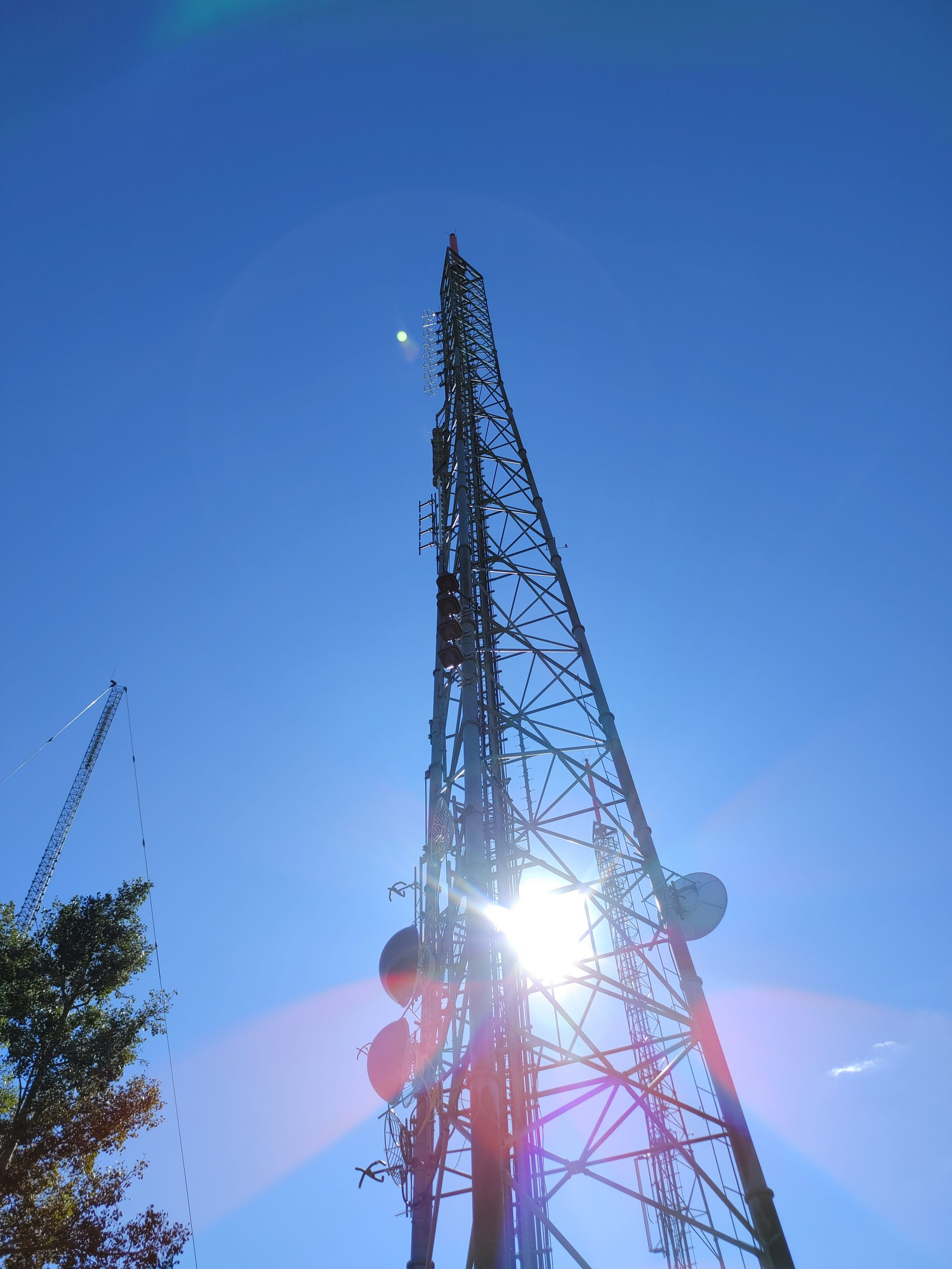
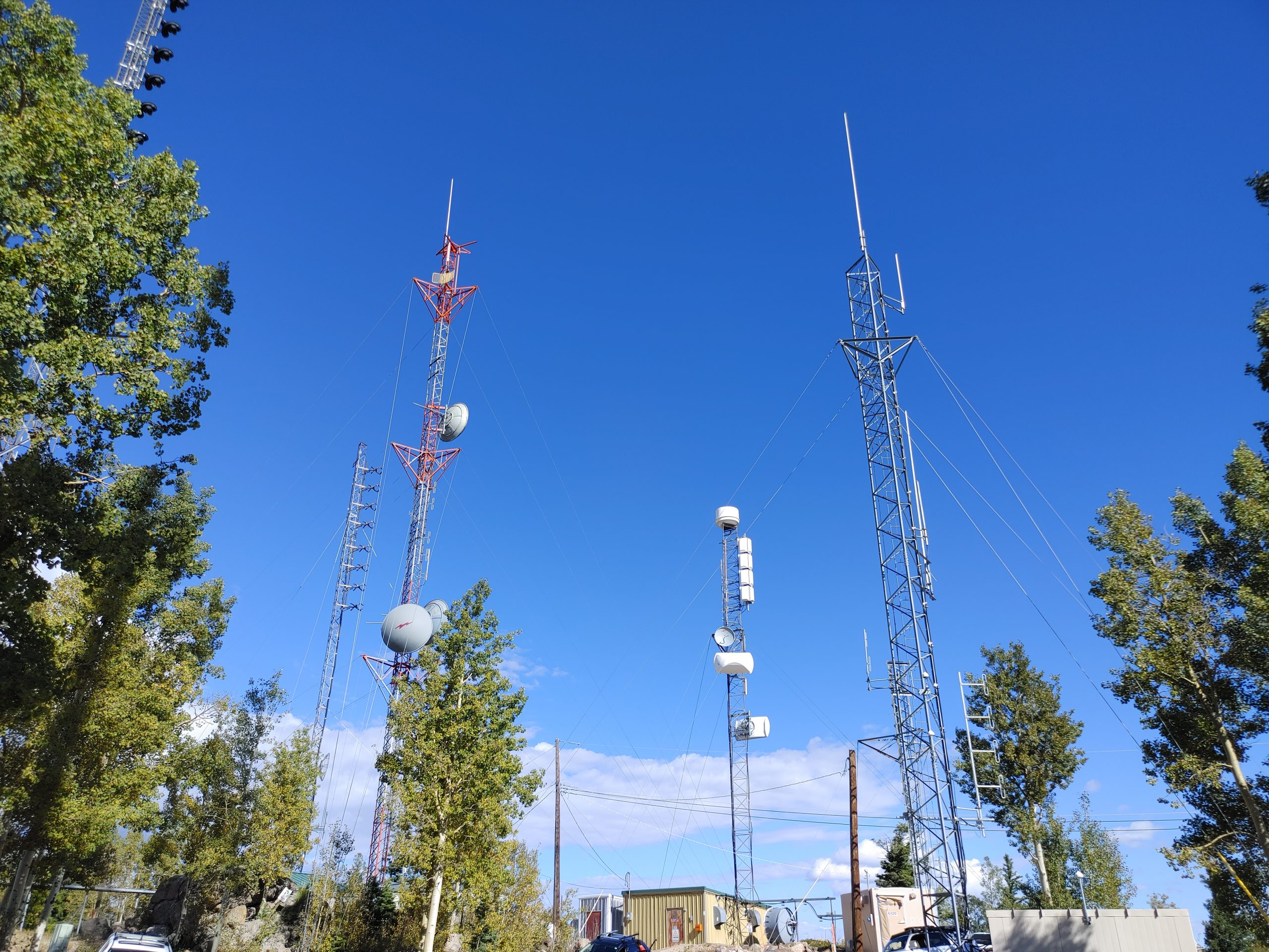
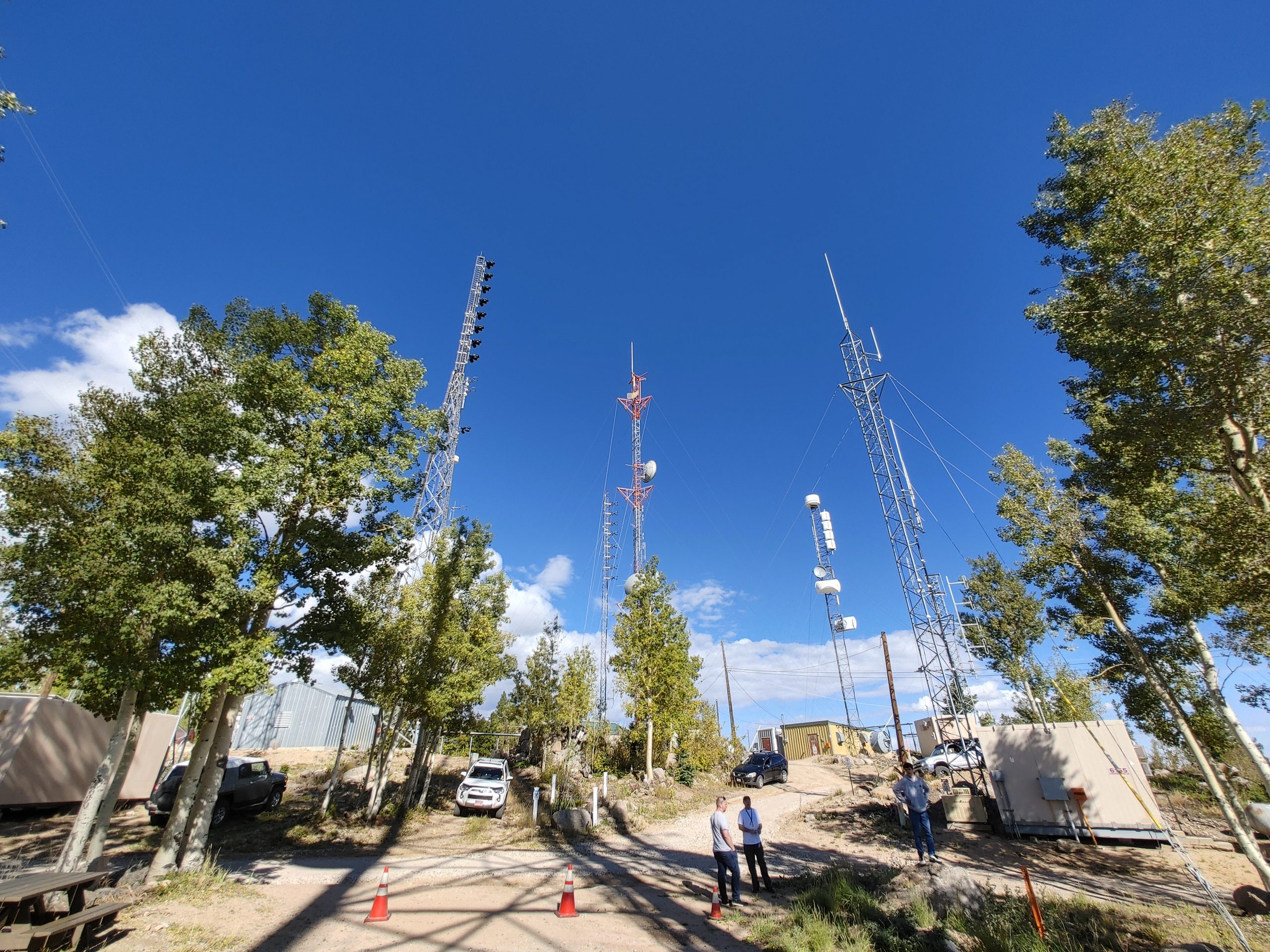
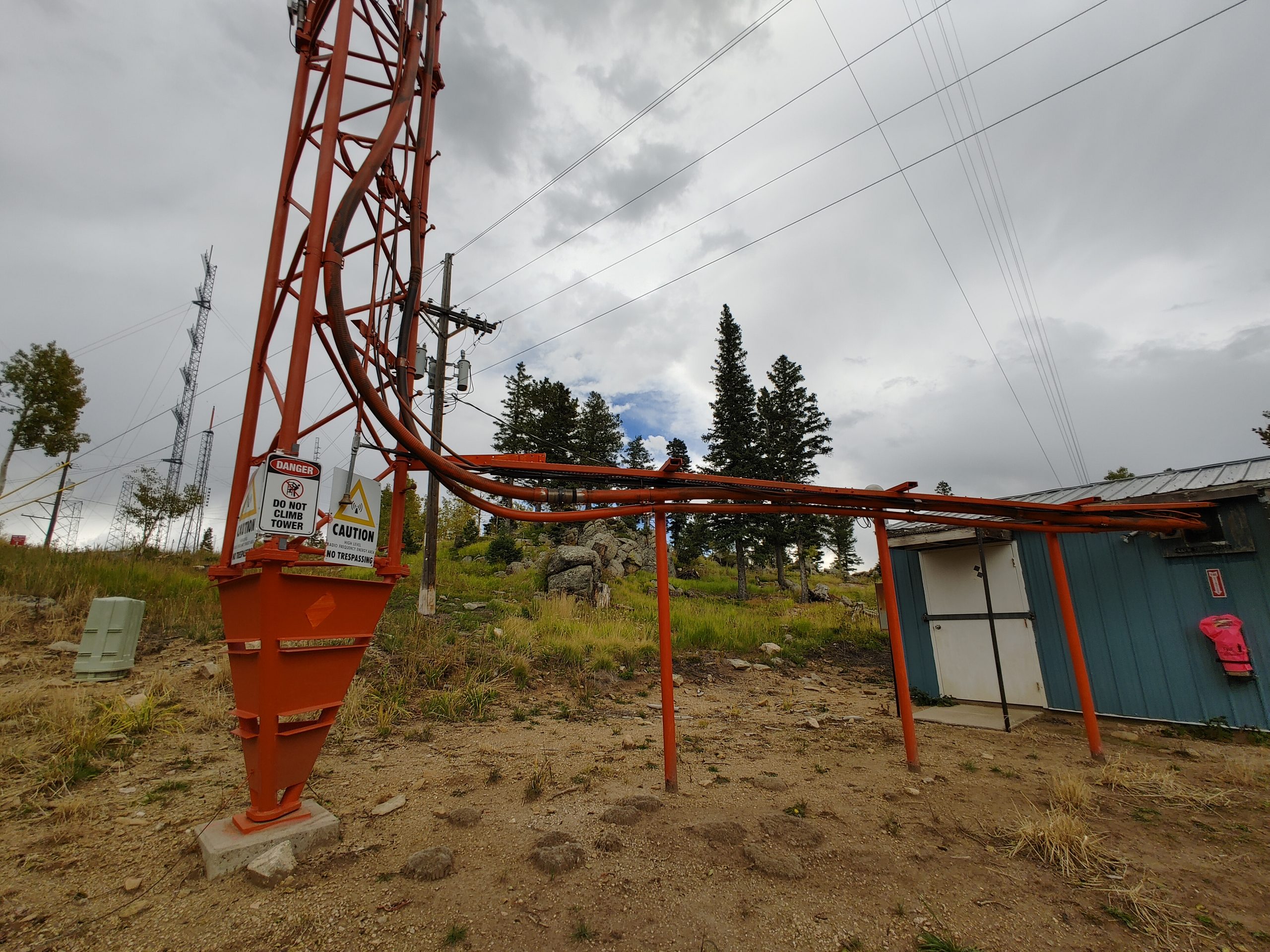
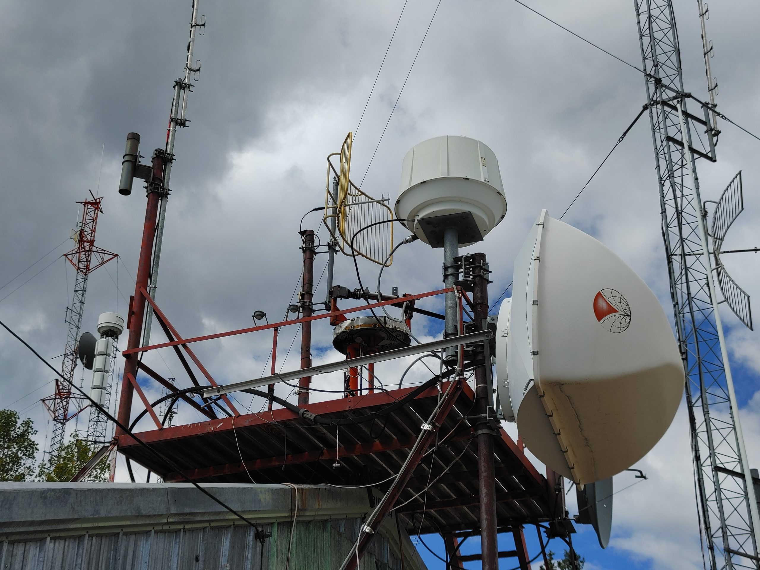
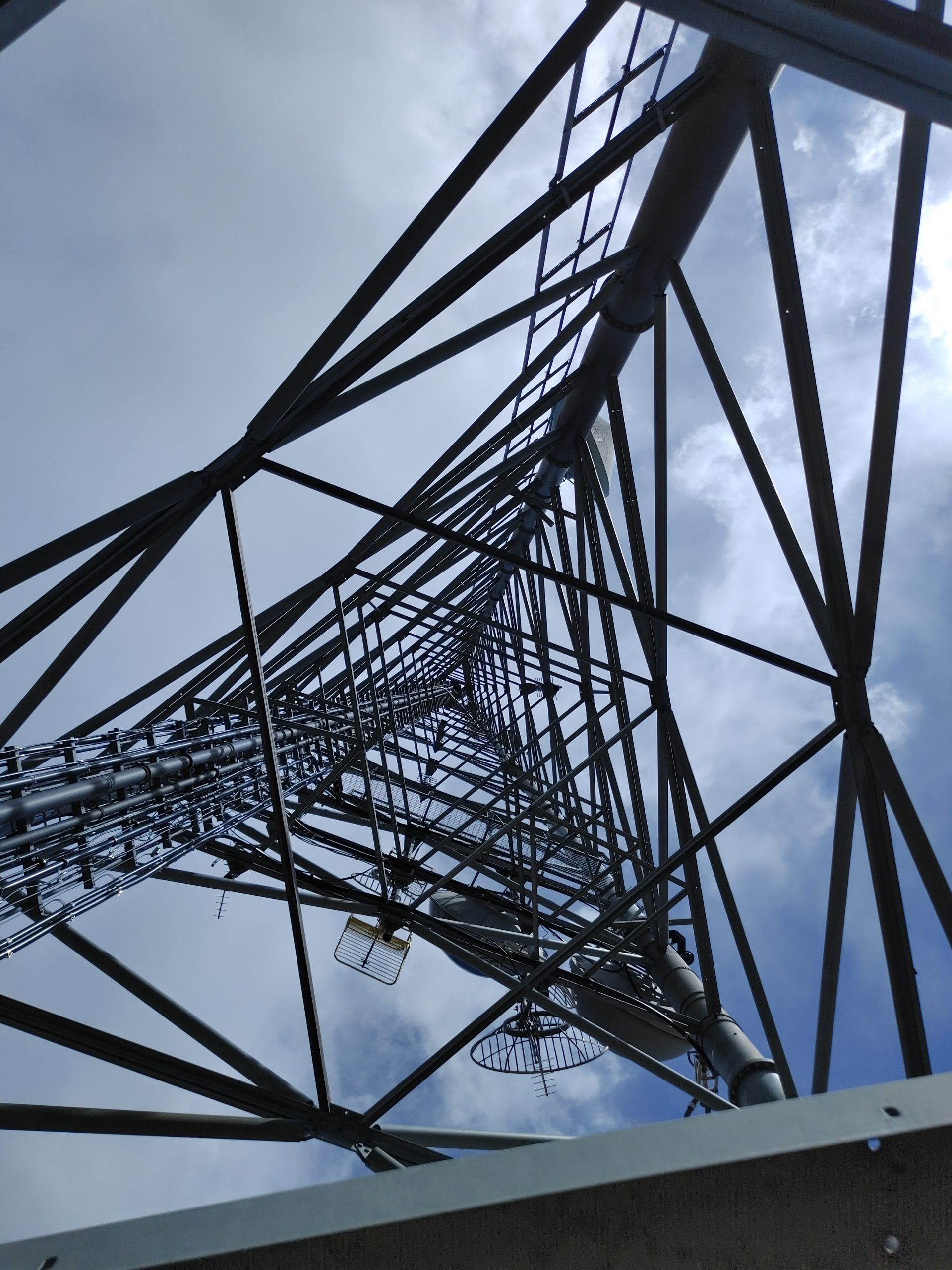
Thanks to Ray and Bill over at Cumulus Media I was given the opportunity to come see another one of Colorado’s most prolific broadcast transmitter sites. This is a 40+ acre antenna farm up at over 9,500ft on Cheyenne Mtn. Colorado Springs. Yes, the one on top of NORAD. This massive complex is home to most of the broadcast FM, television, and two-way radio services in the El Paso county area, including Pueblo and Fountain, though coverage does reach up into the Denver metro area as well.

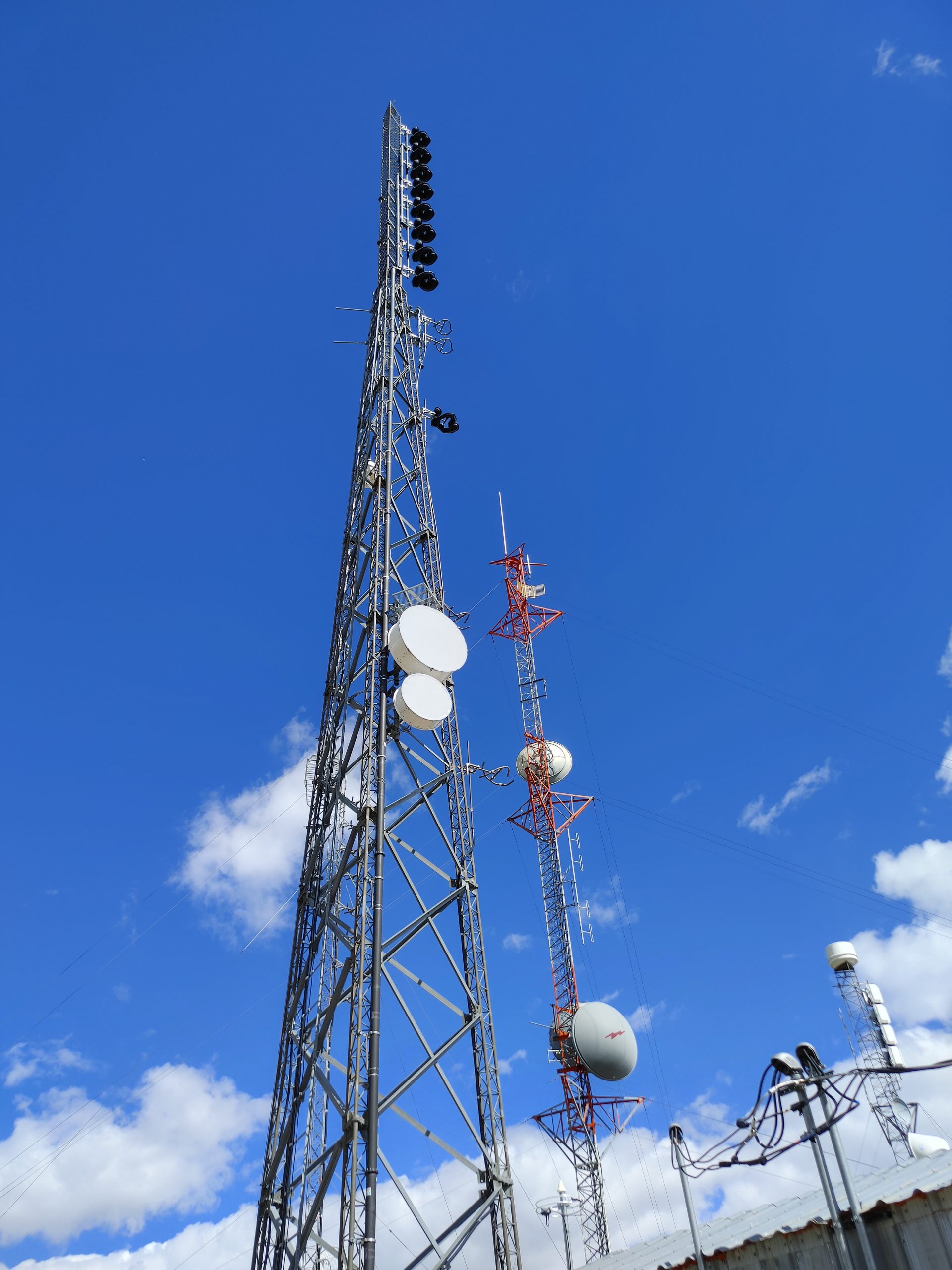
The above is a shot of just one of the main clusters where you can see a smorgasbord of all sorts of towers and antennas. Even the gate up here was interesting as it contained a row of “series” locks arranged in essentially a chain through these plates such that removal of any one of them would break the chain, permitting access through the gate. you’ll see the likes of the fire department, police, and the various broadcast organizations each have their own locks.
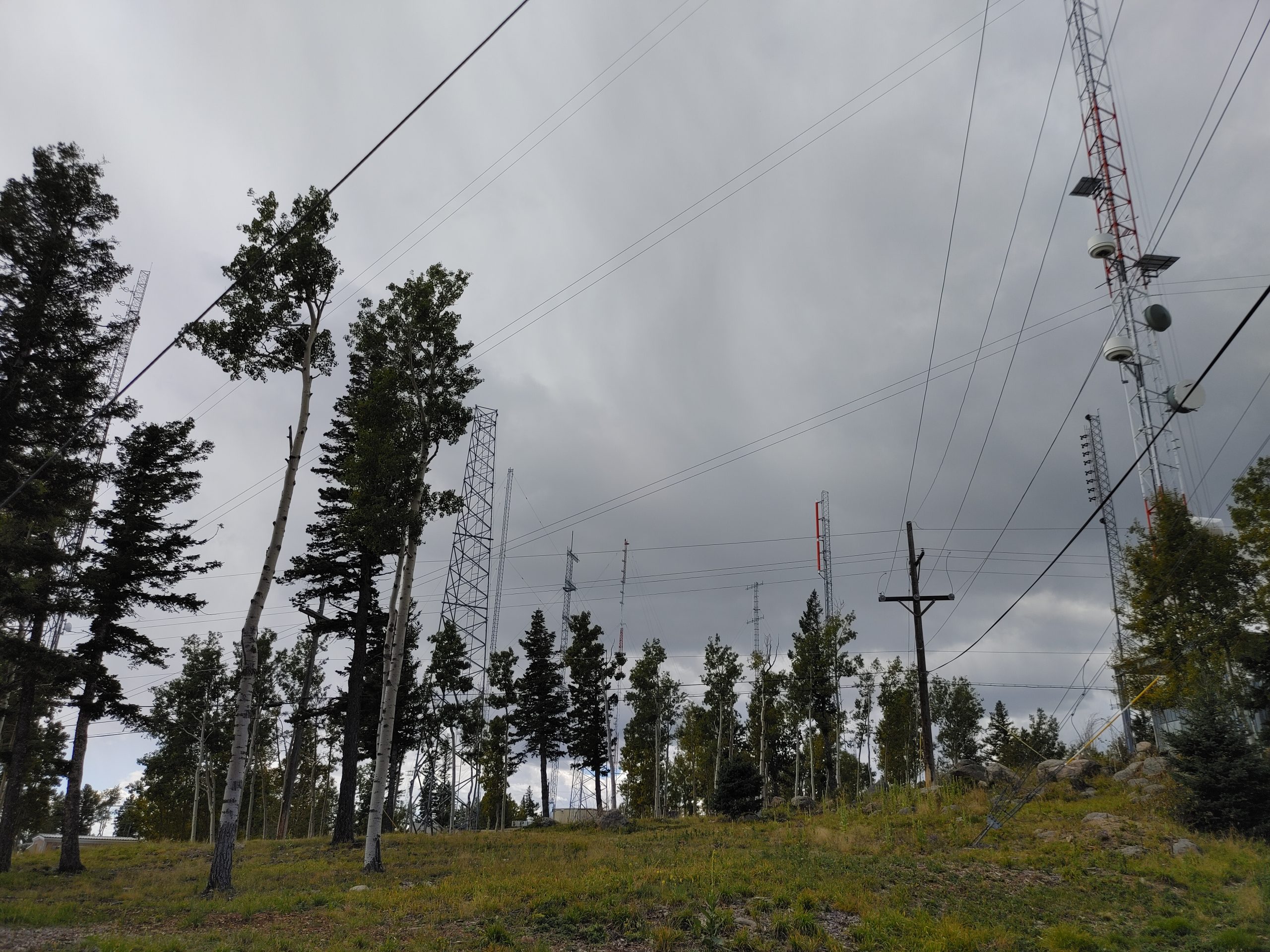
Here’s a bunch of pictures showing the western side of the antenna farm. There were so many towers here I didn’t even bother counting them all.
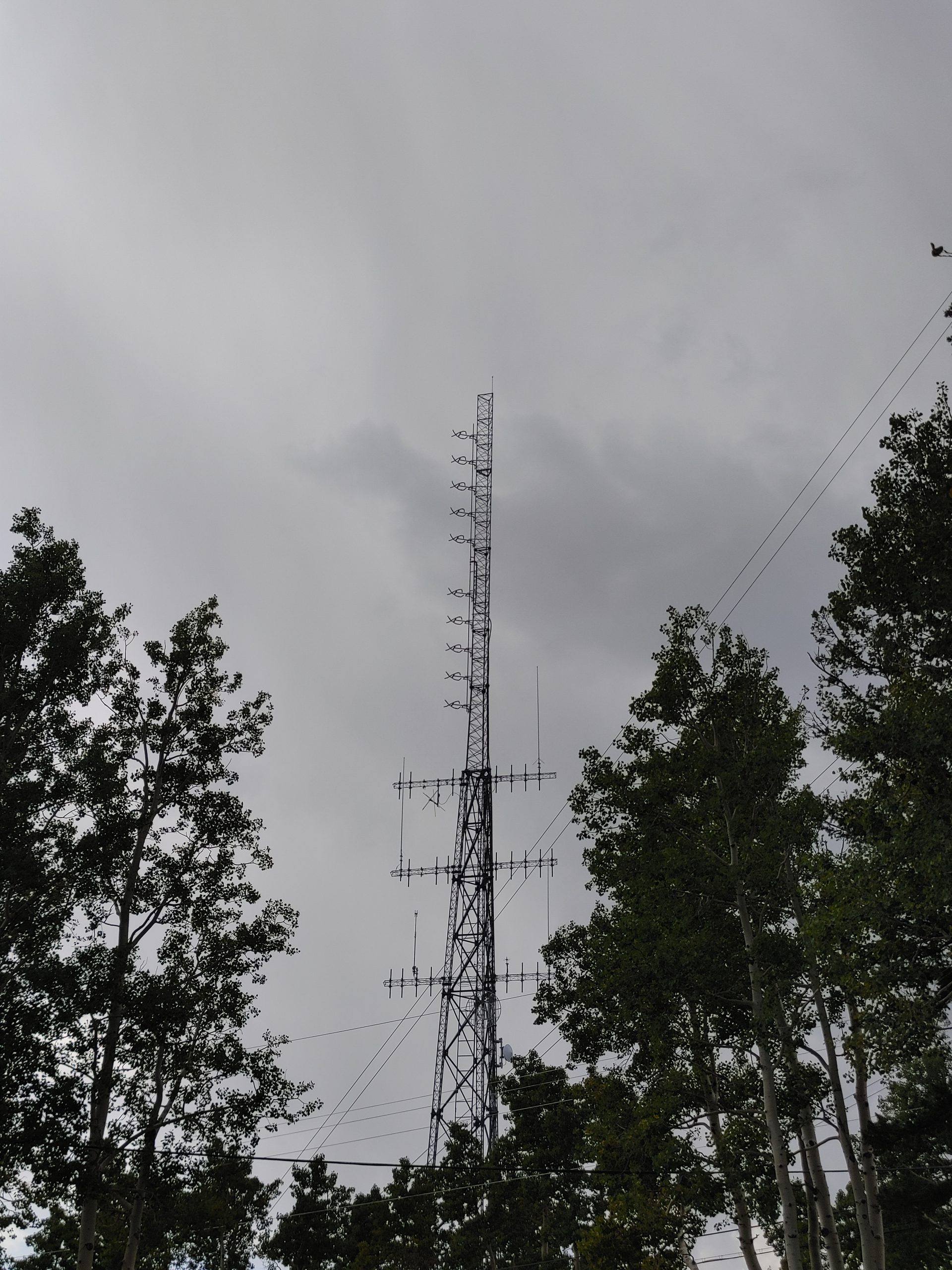

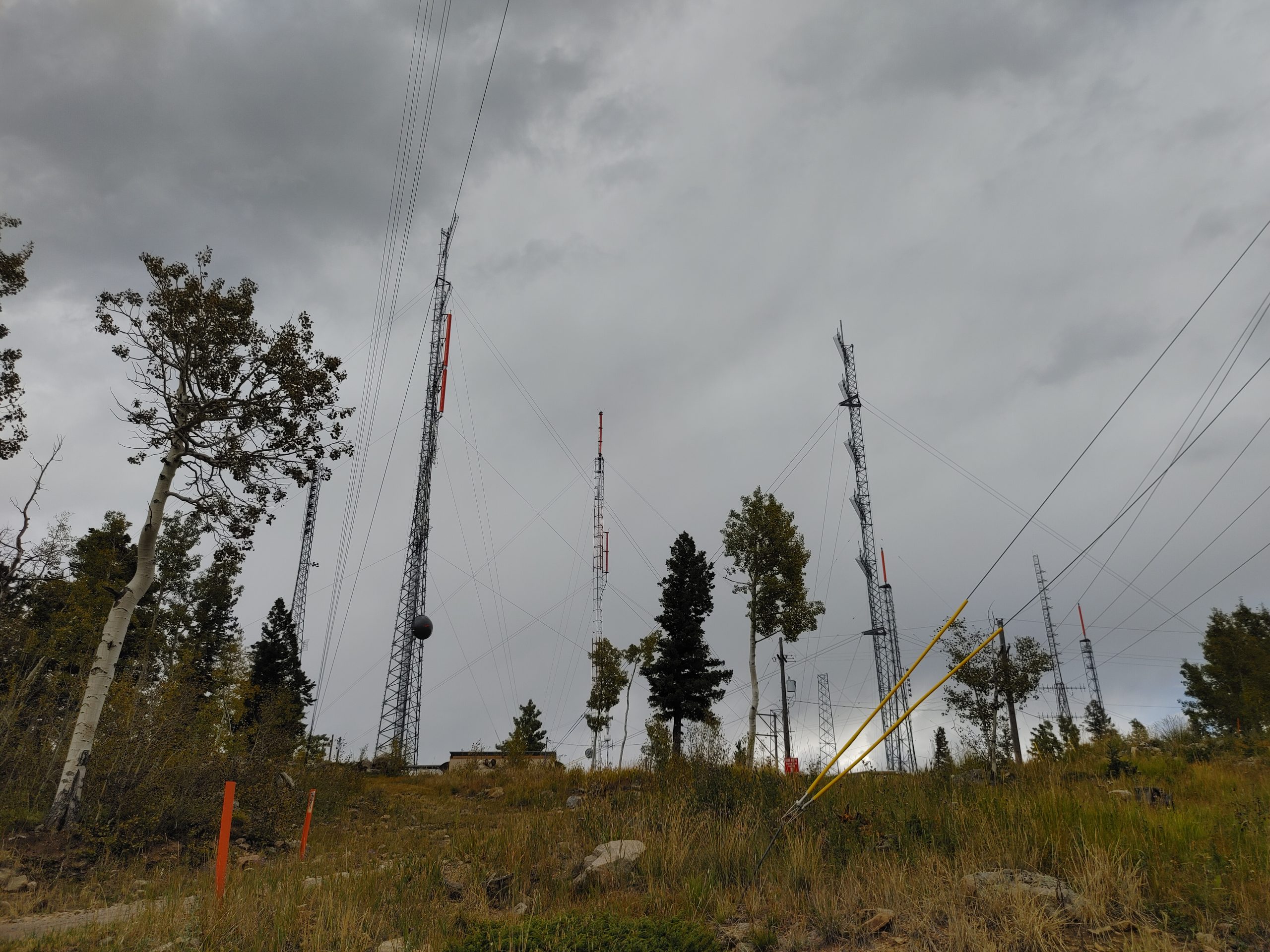


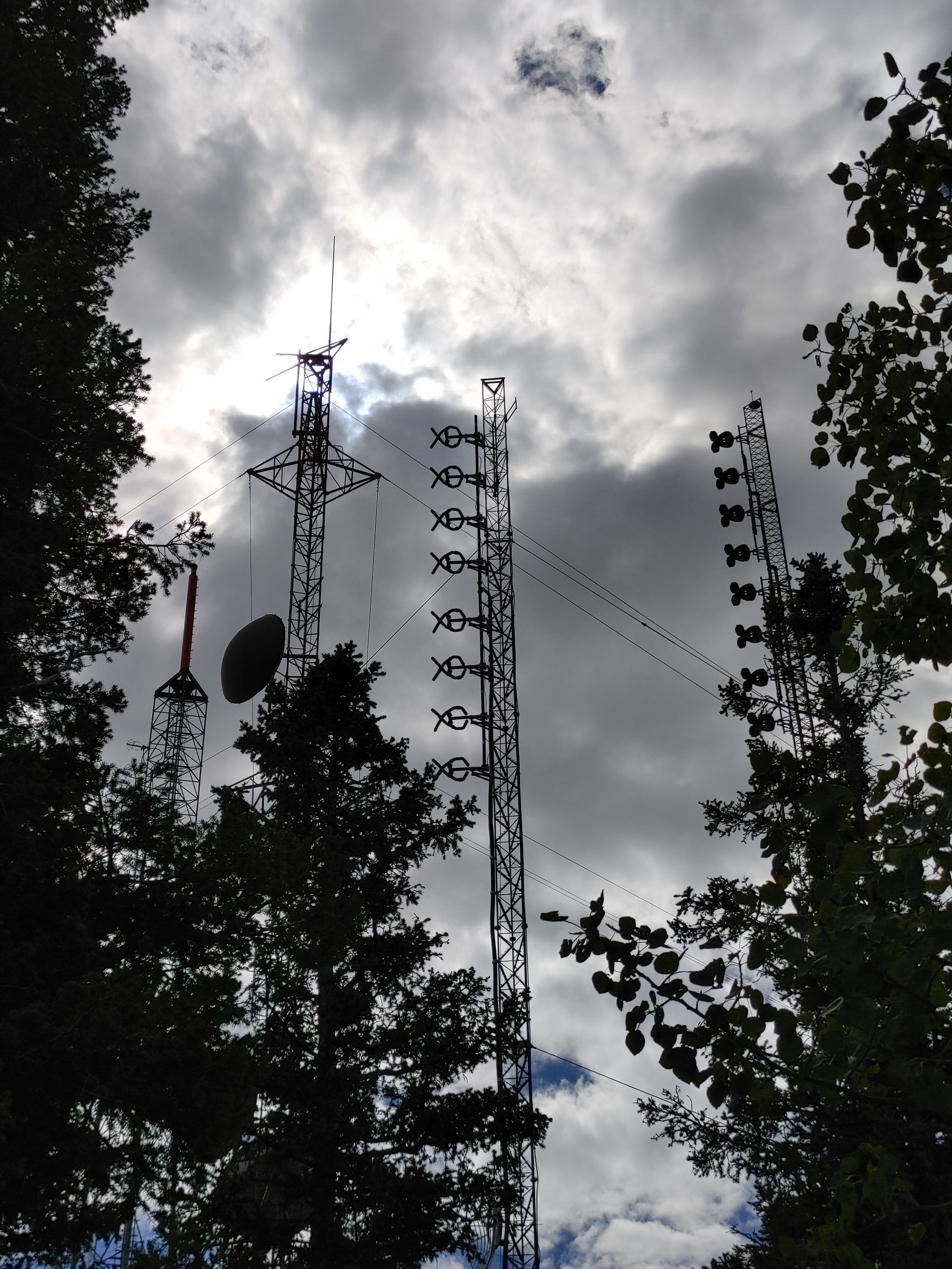

You’ve probably noticed by now that almost all of these antennas actually consist of multiple stacked elements. These are called colinear arrays. These are used to increase the gain towards the horizon whilst maintaining an omni-directional radiation pattern. See how this effect works via the images below. First is the radiation pattern for a single antenna element (roughly).
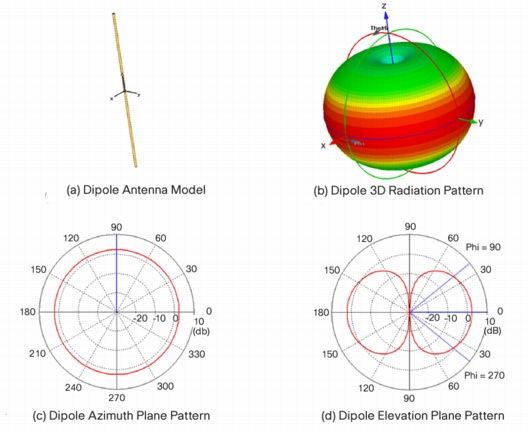
The above image shows how the wavefront from each pattern add collectively in a given direction. In this case, the angle would be zero, or maybe slightly down rather than upward. An interesting note on this point is that the spacing of the elements affects the magnitude and quantity of radiation lobes. Generally going above a half wavelength spacing will cause very large side-lobes and deep nulls. These are already present in even the standard half-wavelength spaced arrays. Hence, modern antenna solutions have started providing something called “null-fill” which essentially staggers the spacing of the elements to make the coherence less than perfect. This slightly reduces the gain of the main lobe, but also greatly reduces the nulls, “filling” in the radiation pattern a bit. This typically helps most with improving signal quality to listeners close to or under the tower.
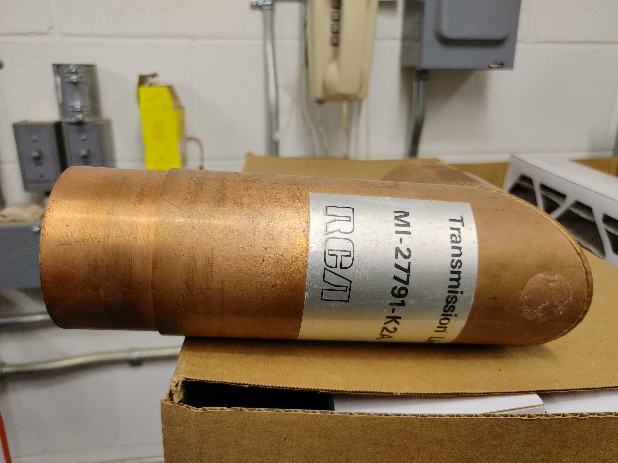
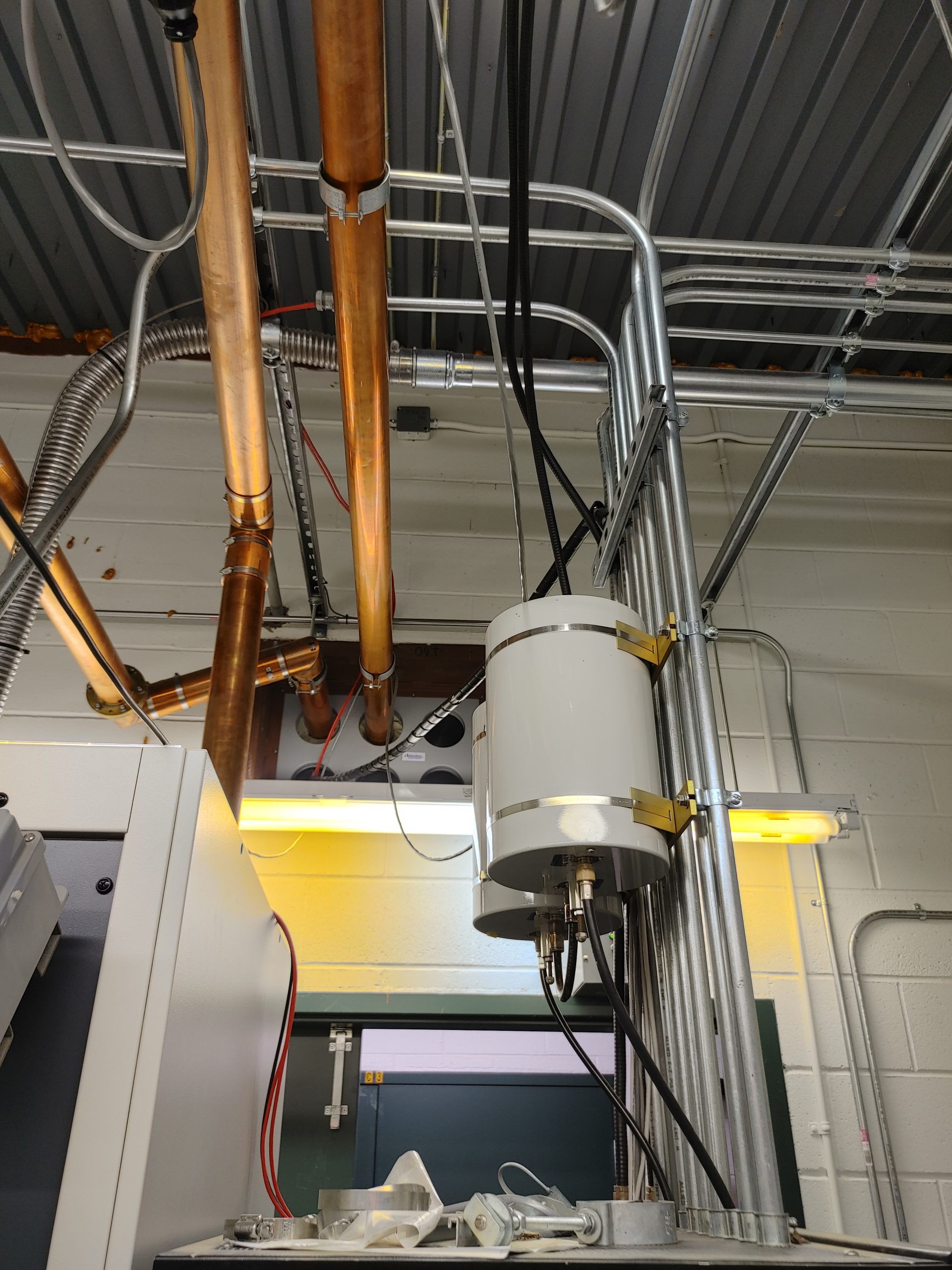
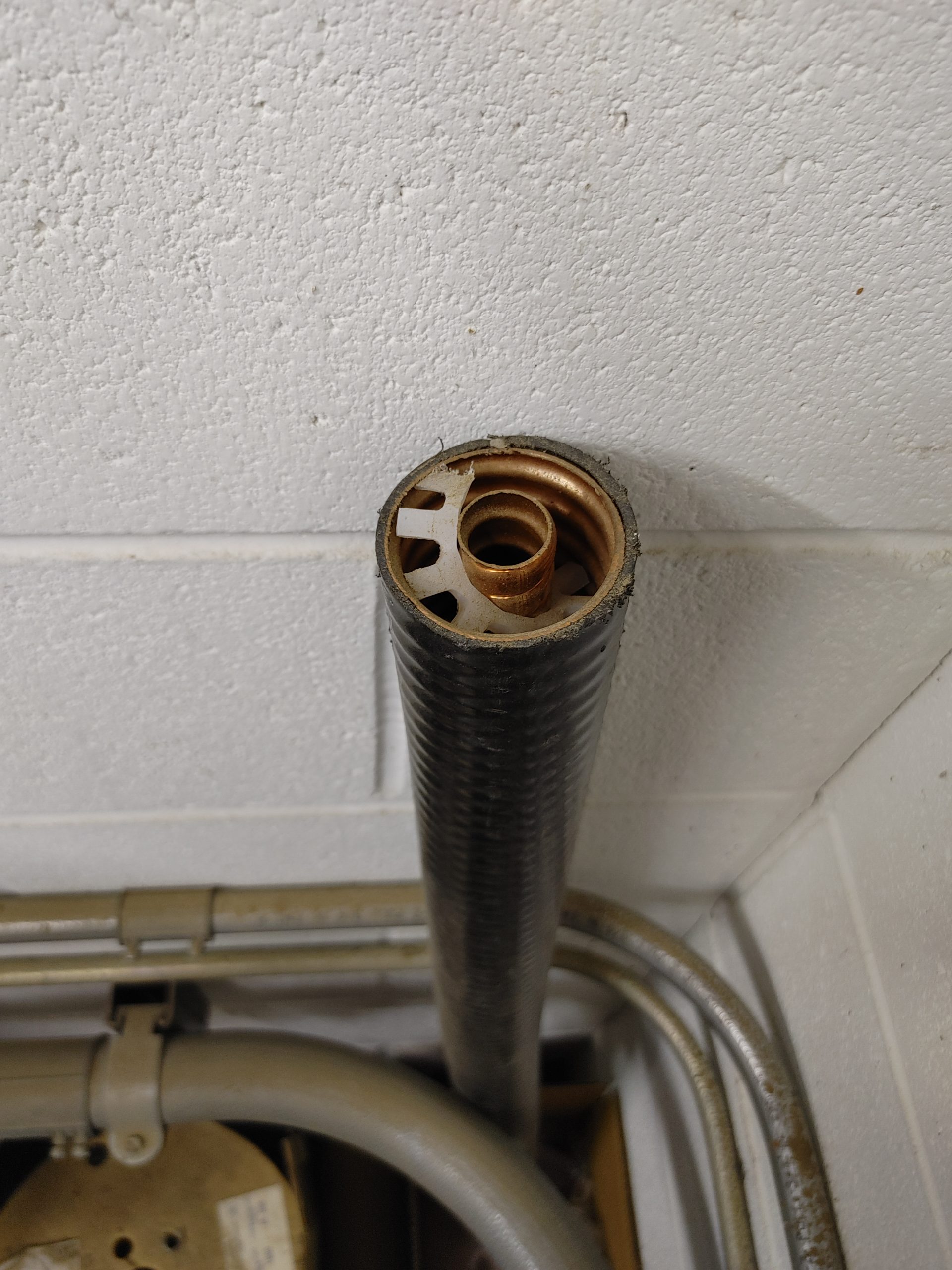
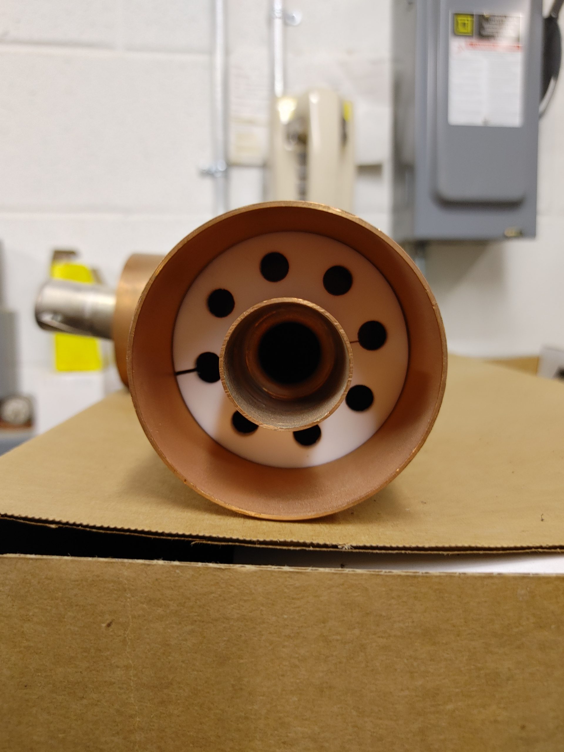
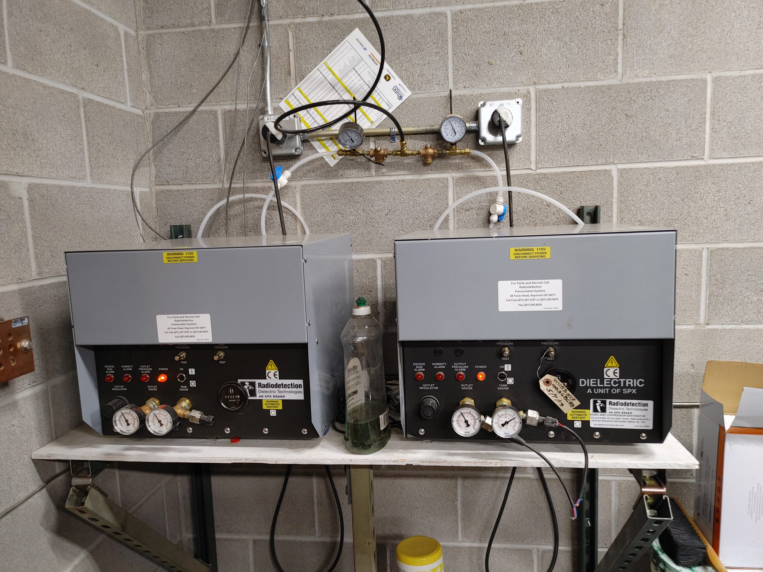
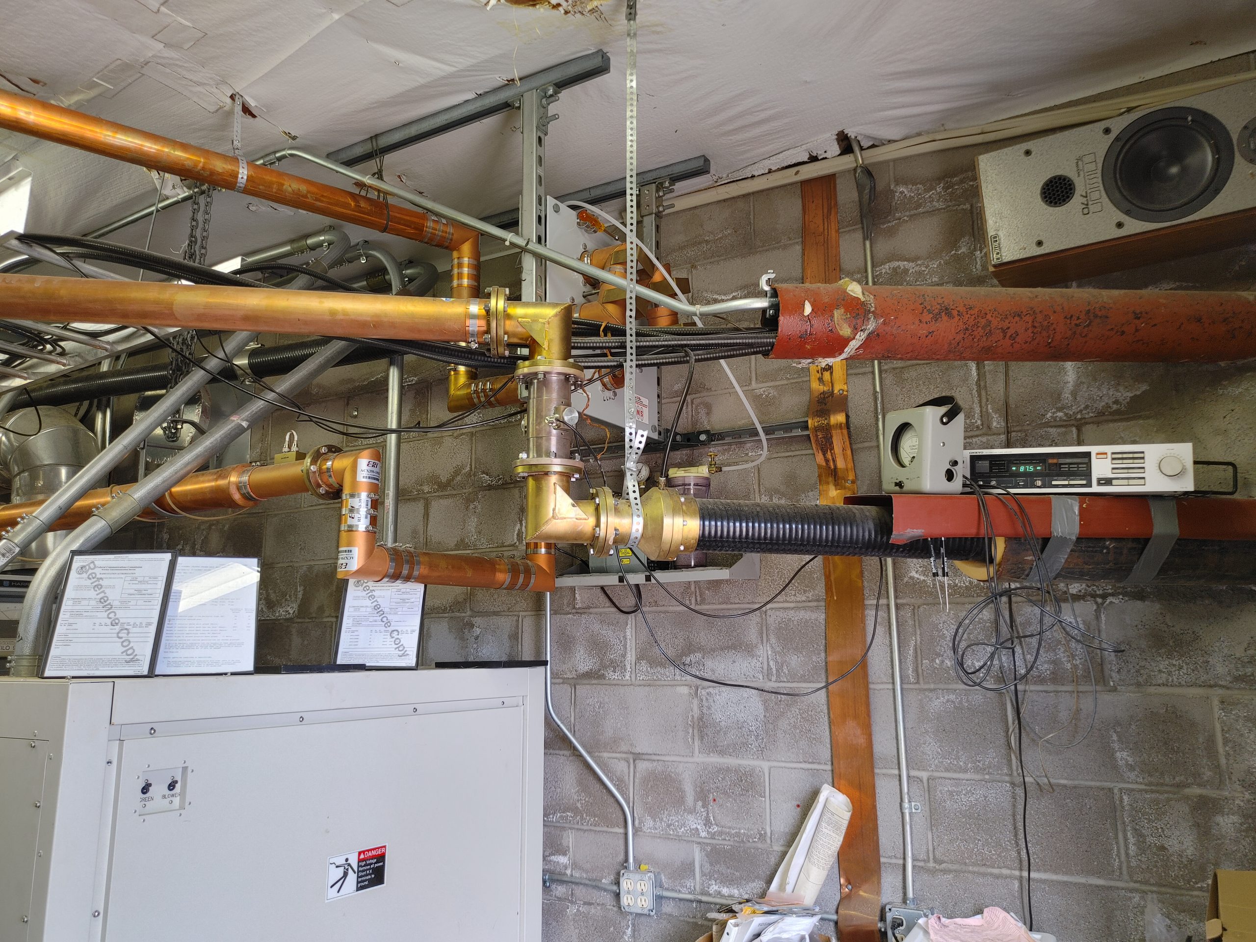
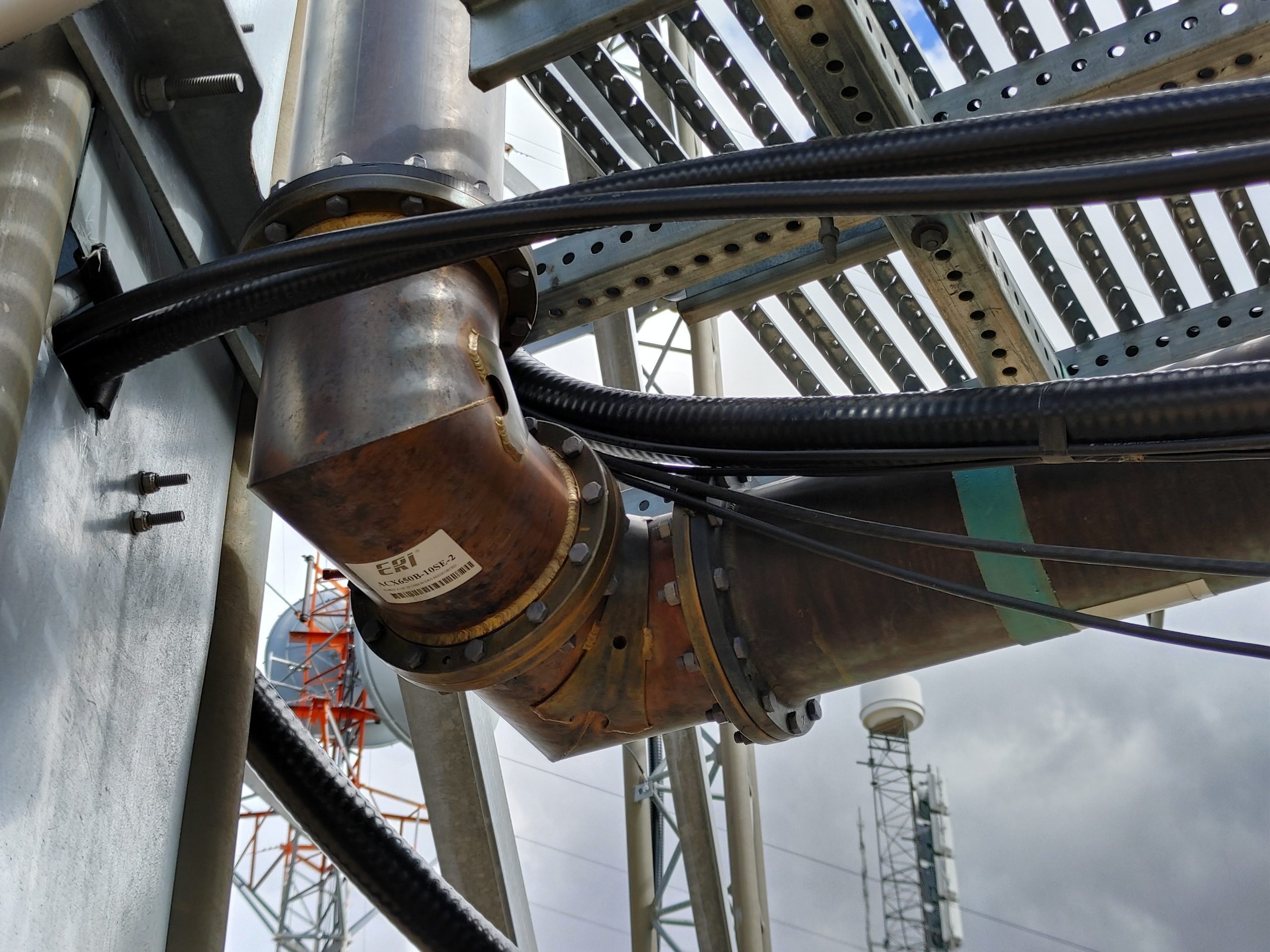
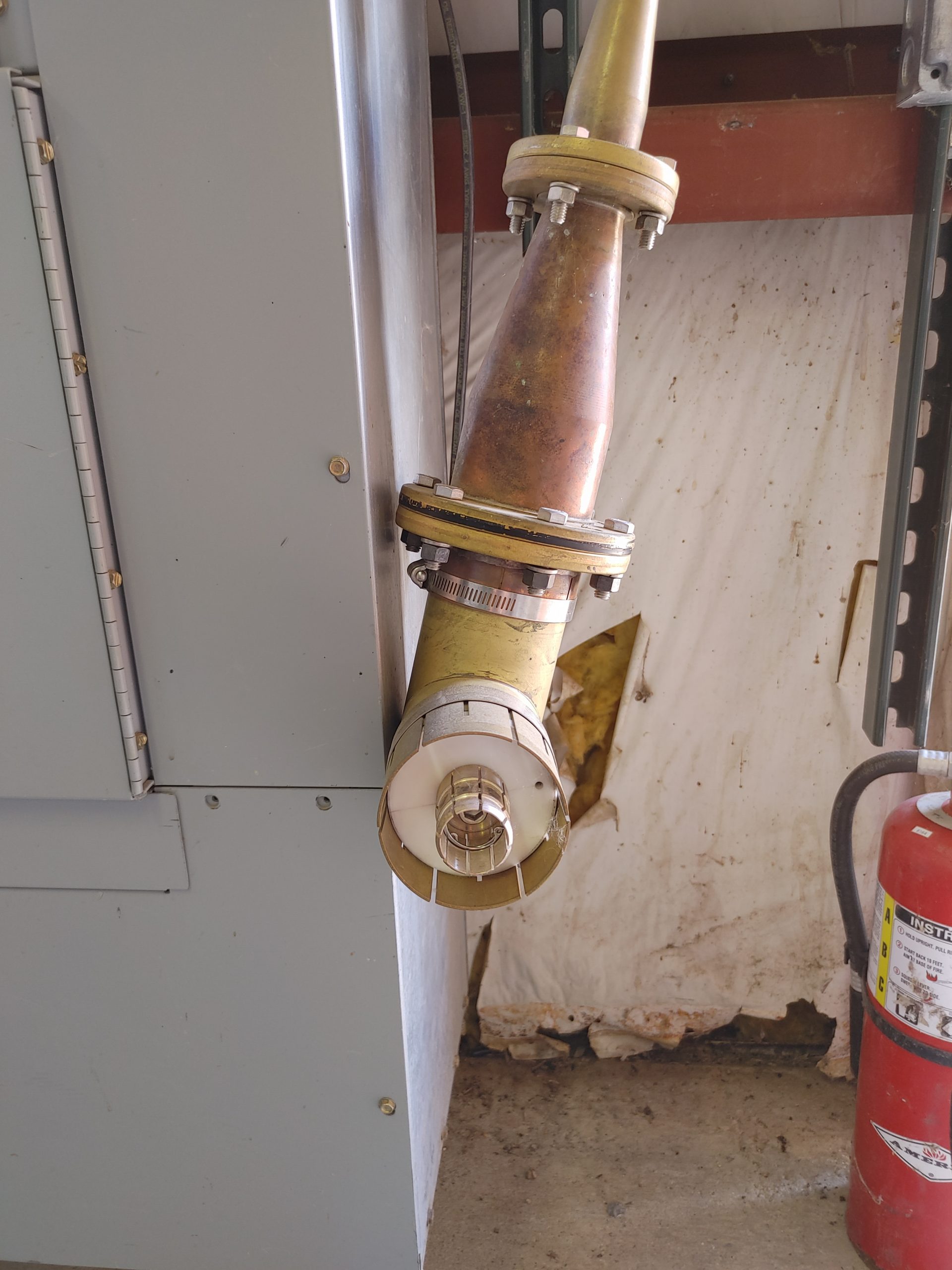
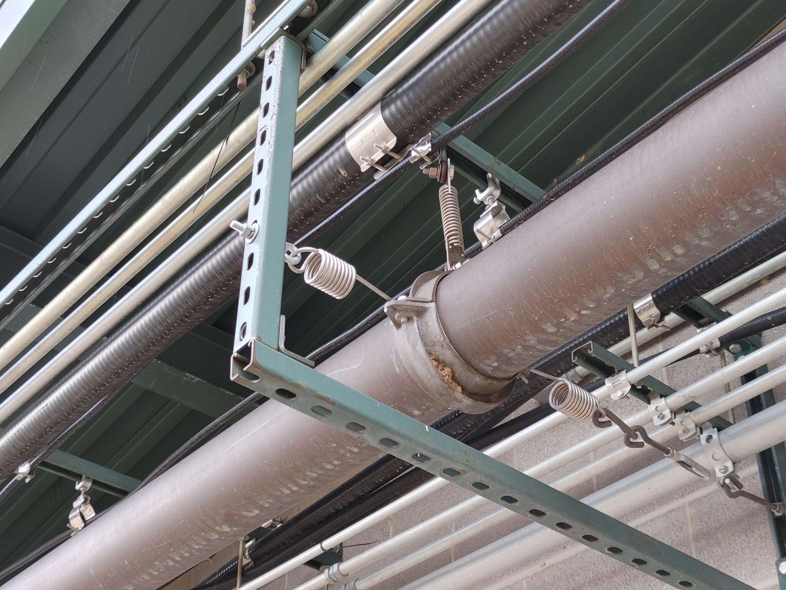
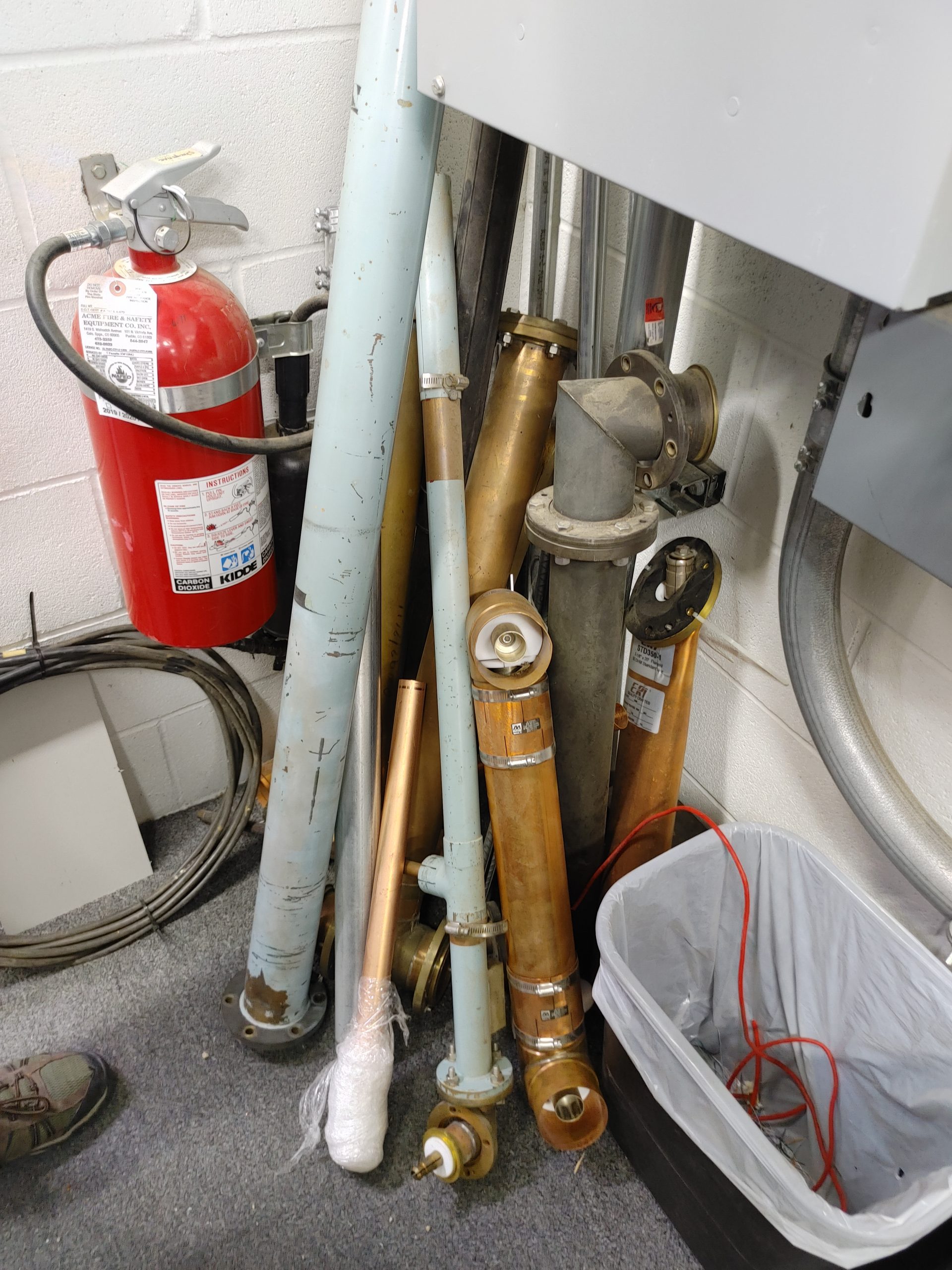
Now that we’ve had a good look at most of the outside site, let’s examine some of the feeder systems. These are ABSOLUTELY INSANE. Most of these stations typically produce about 25kW of power, so the feed lines are made of copper piping to be able to handle the voltages and currents. Yes, this is coaxial PIPE. not wave-guide, coax. This consisted of anything from 3-6″ outside diameter copper pipe bolted together in various section length through flanges. The center conductor was typically a 1-2.5″ copper pipe suspended inside via the occasional nylon spacer ring. Inside, the center conductors of individual sections are joined with these flowering rods called “bullets”. These essentially allow two pipes to fit snugly on either side over the bullet. Since this feeder must be very low-loss and precisely matched, any moisture ingress would be disastrous, causing fires and rapid corrosion. Because of this, all of the outside piping is pressurized with an inert gas to prevent any moisture building up. Lastly, all of the outside piping is also suspended on springs to allow expansion and contraction with temperature changes without shearing any mounts or bending sections.
To give you an idea of the kind of damage that can be caused when this fails, Ray told me a story about how they once had a bullet joint fail due to flexing over the years work hardening the middle. This bullet snapped, causing an open-circuit and lots of arcing. This was severe enough to completely melt several feet of the center conductor pipe and nylon spacers, forcing the entire feed line to be disassembled and repaired.
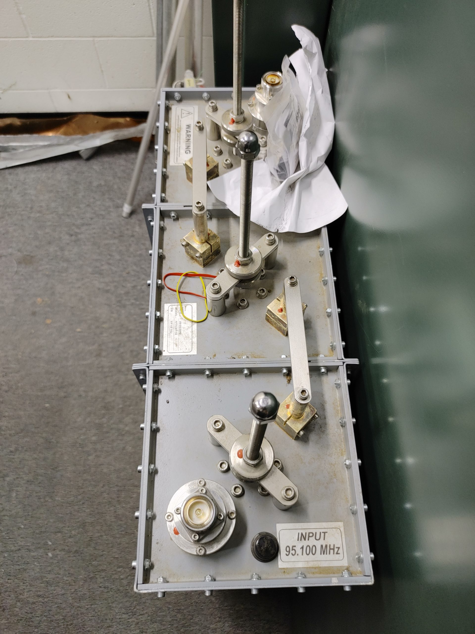
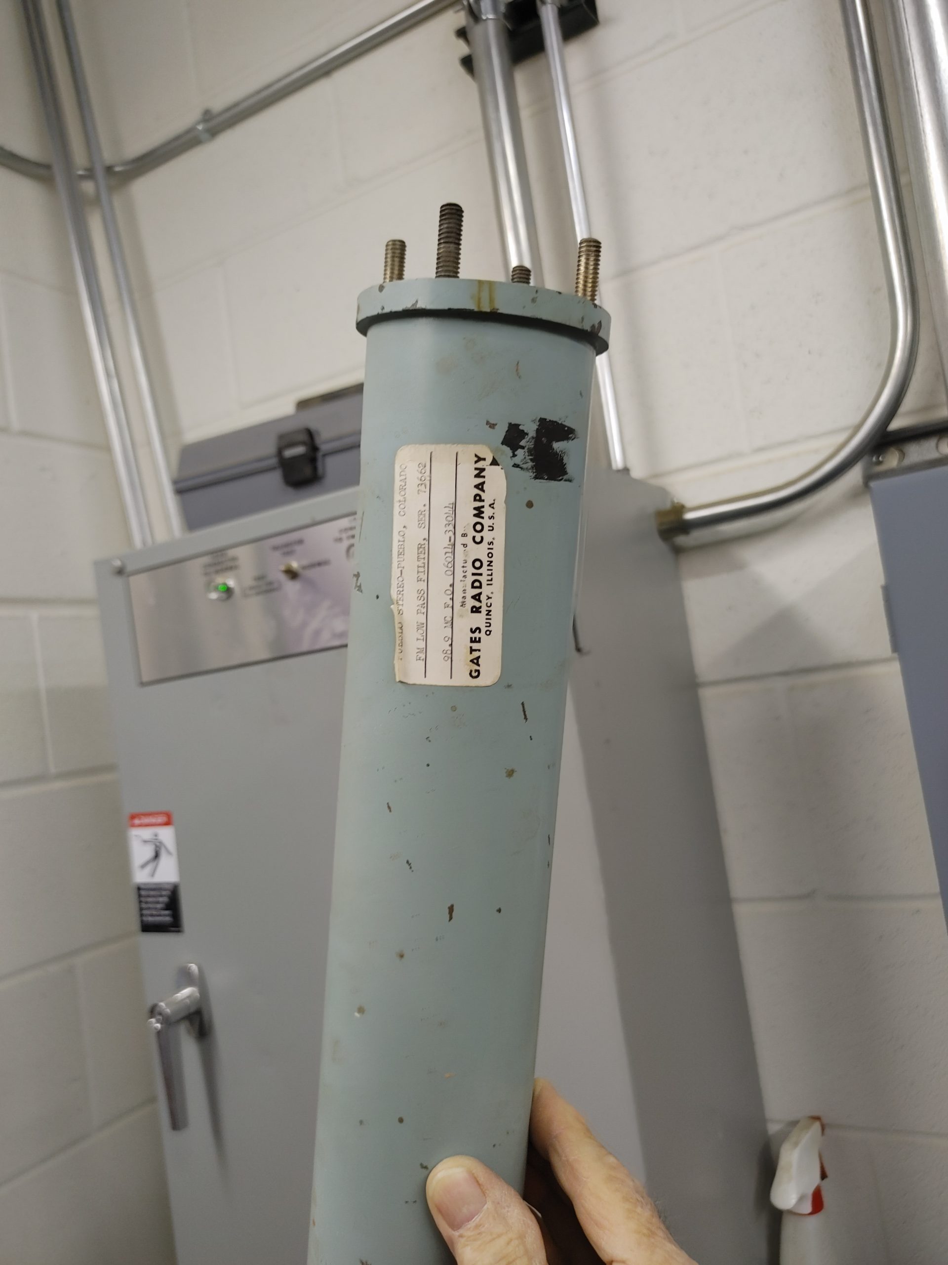
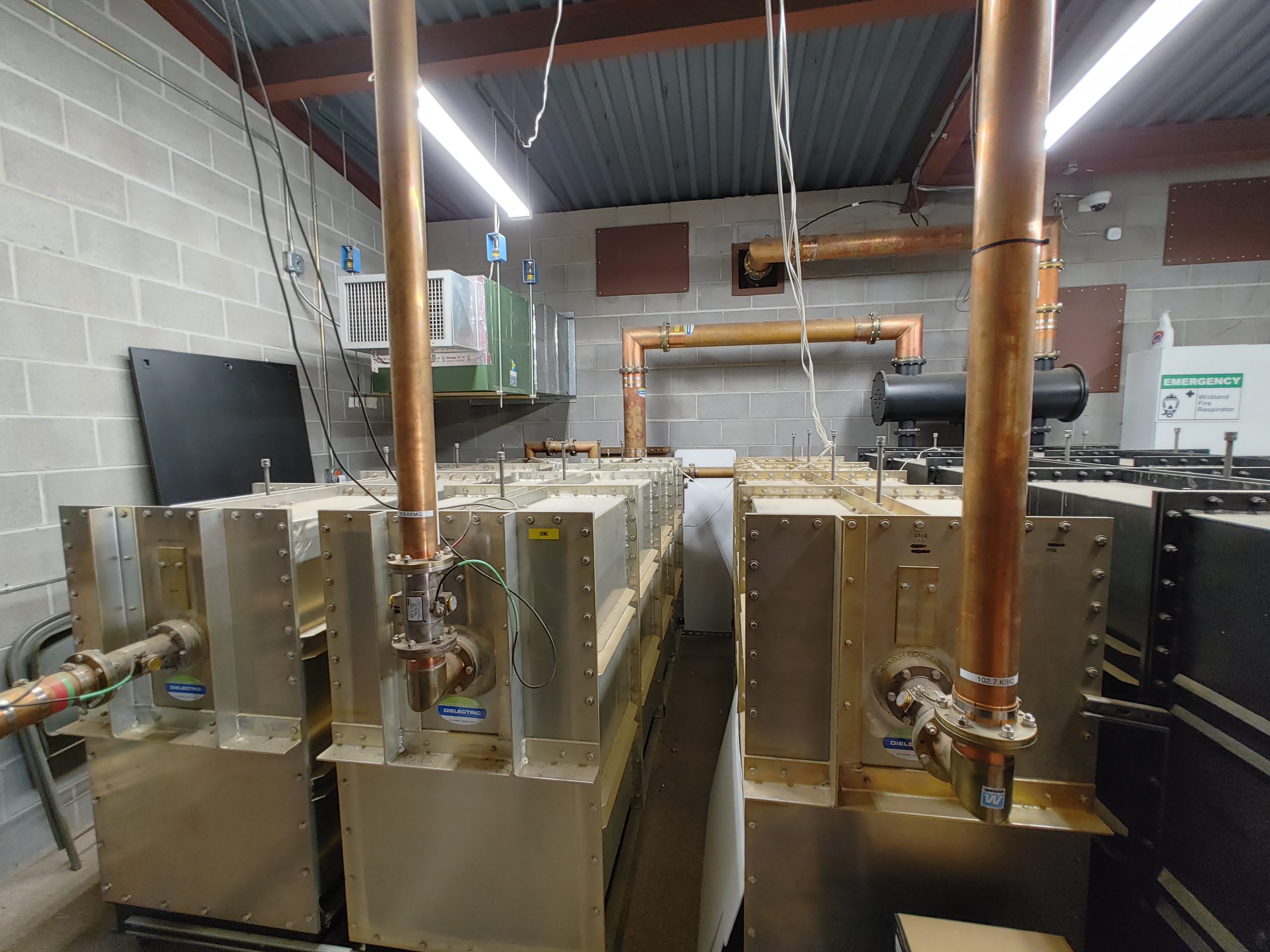
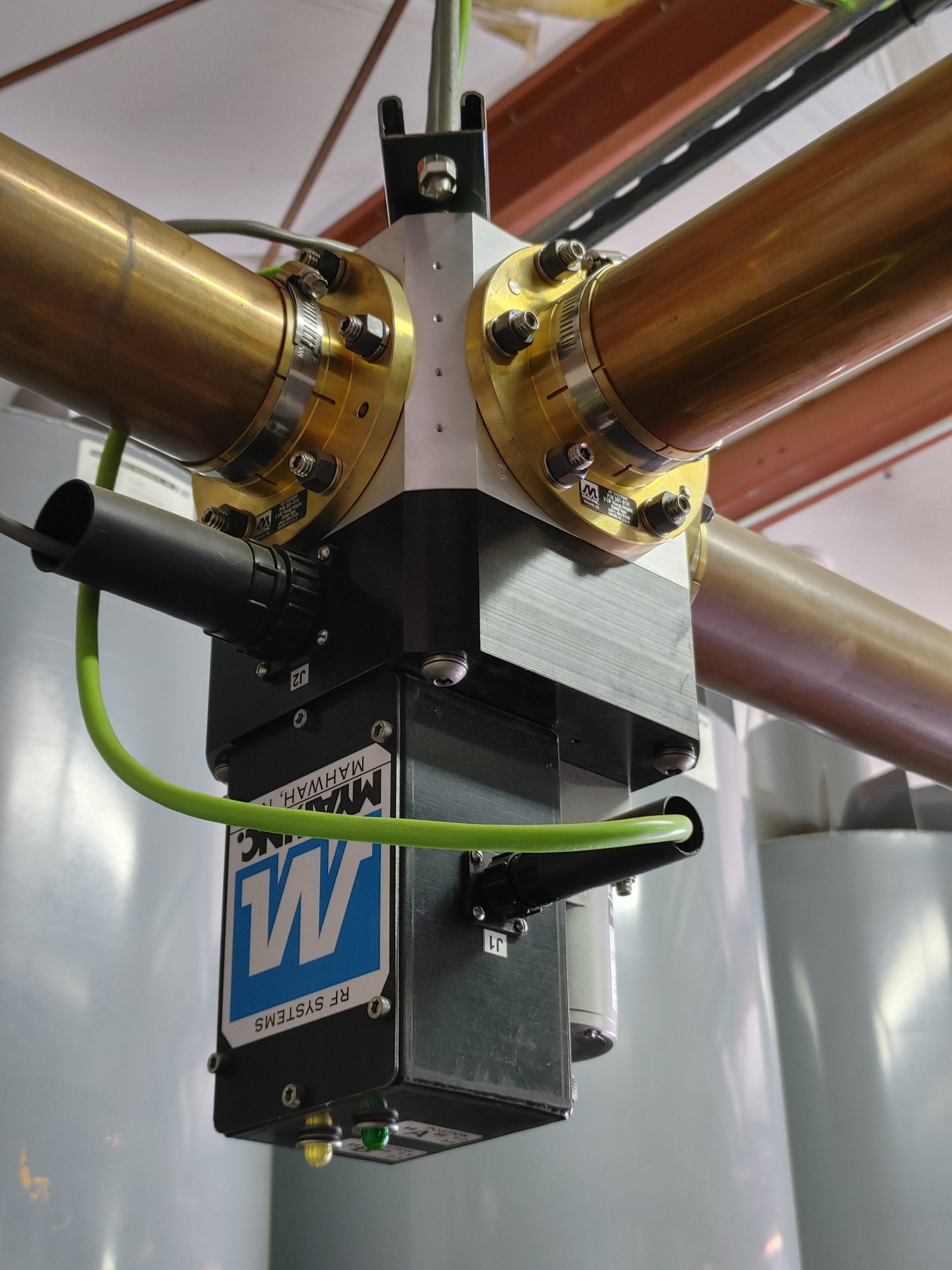
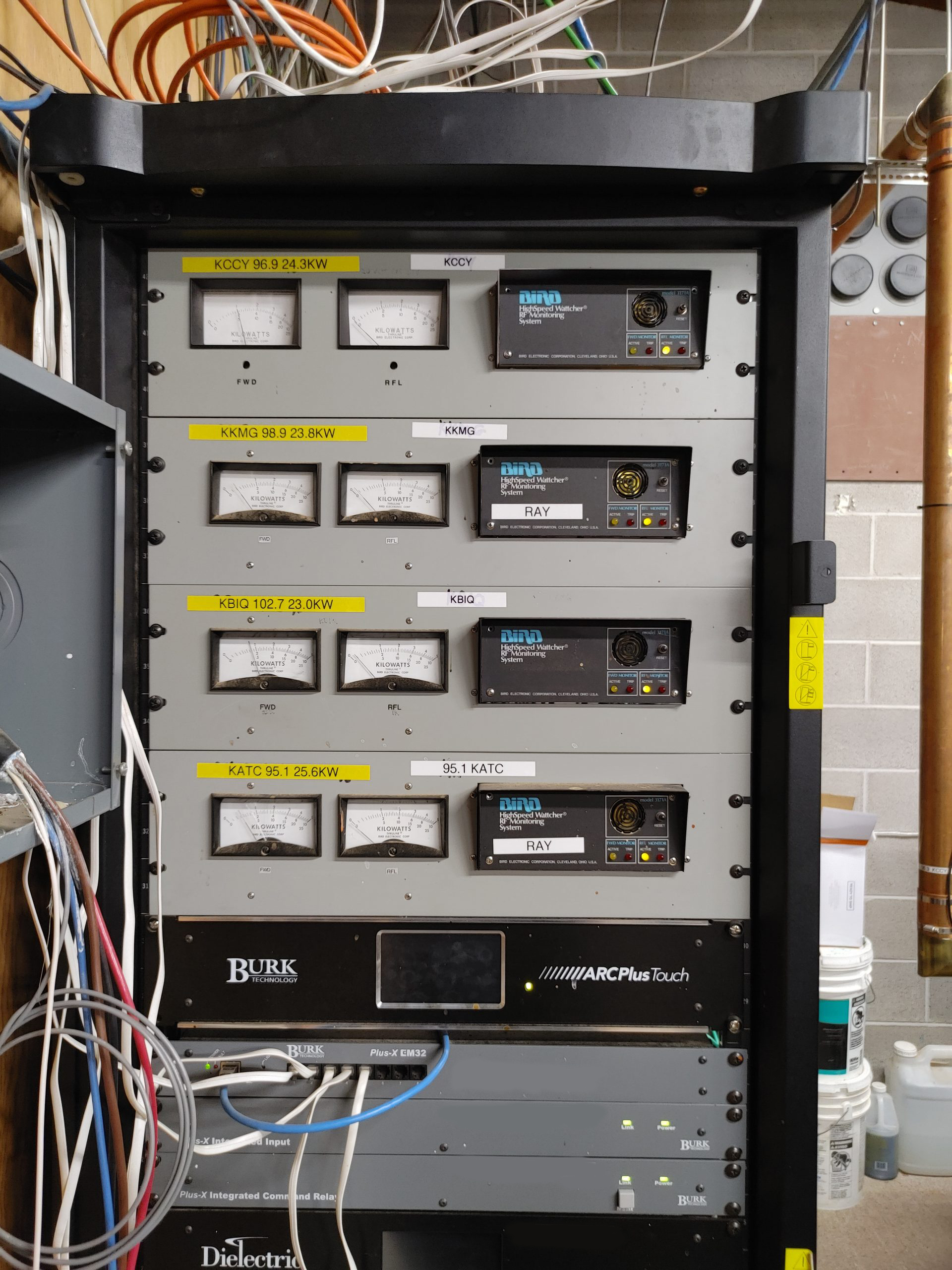
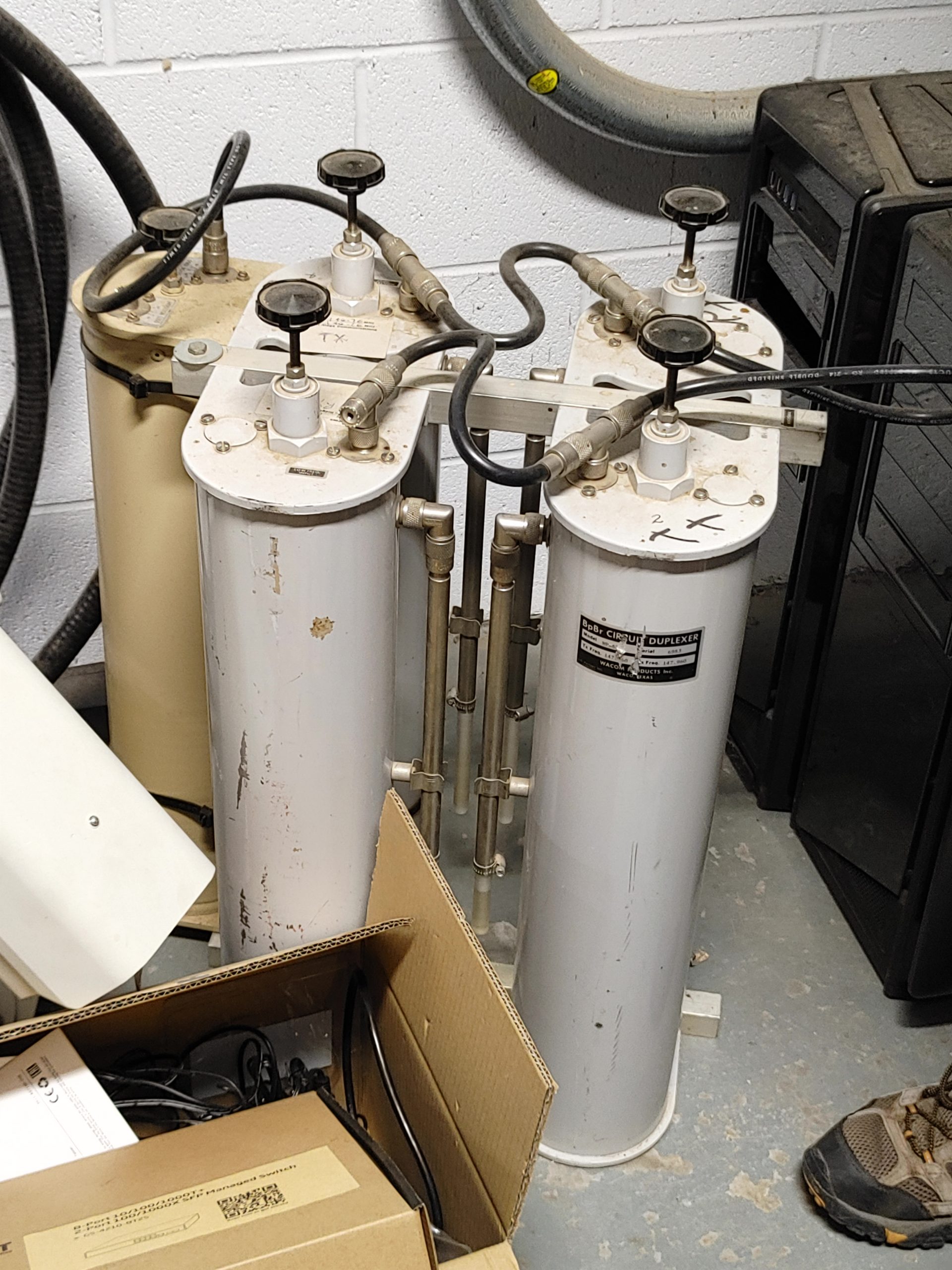
To make things even more complicated, most of these stations also had backup antennas, backup transmitters, and dummy loads. This means MASSIVE transfer switches. Lastly, many of these transmitters are also combined onto a single antenna array, requiring huge cavity filter banks to combine the high powers.
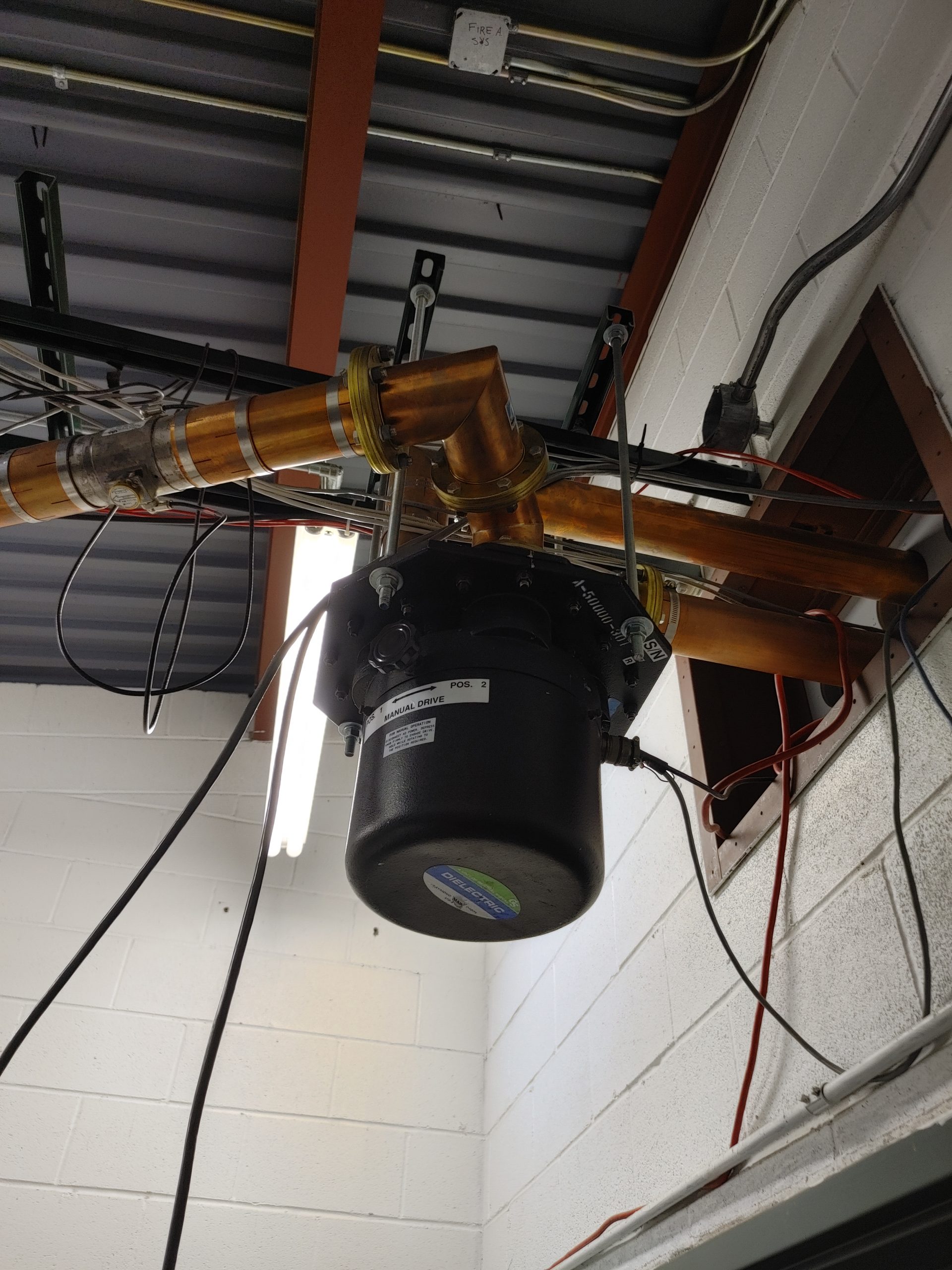


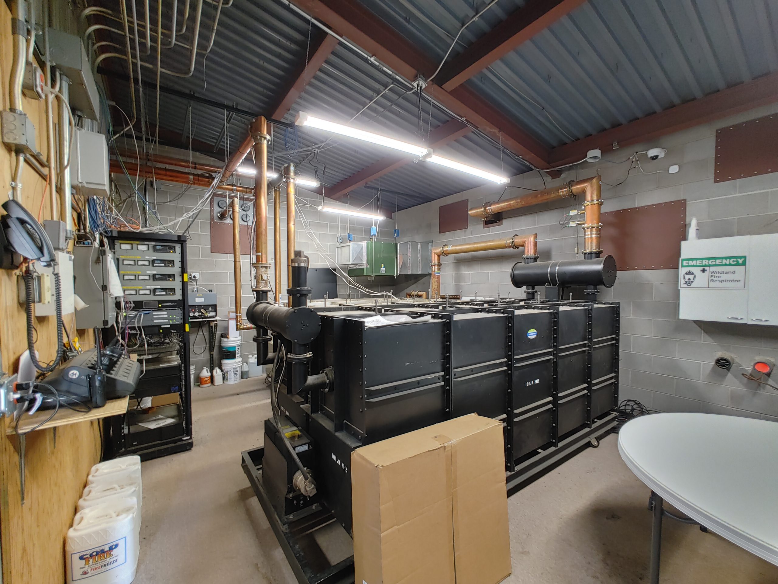

Note pipe to Heliax transition


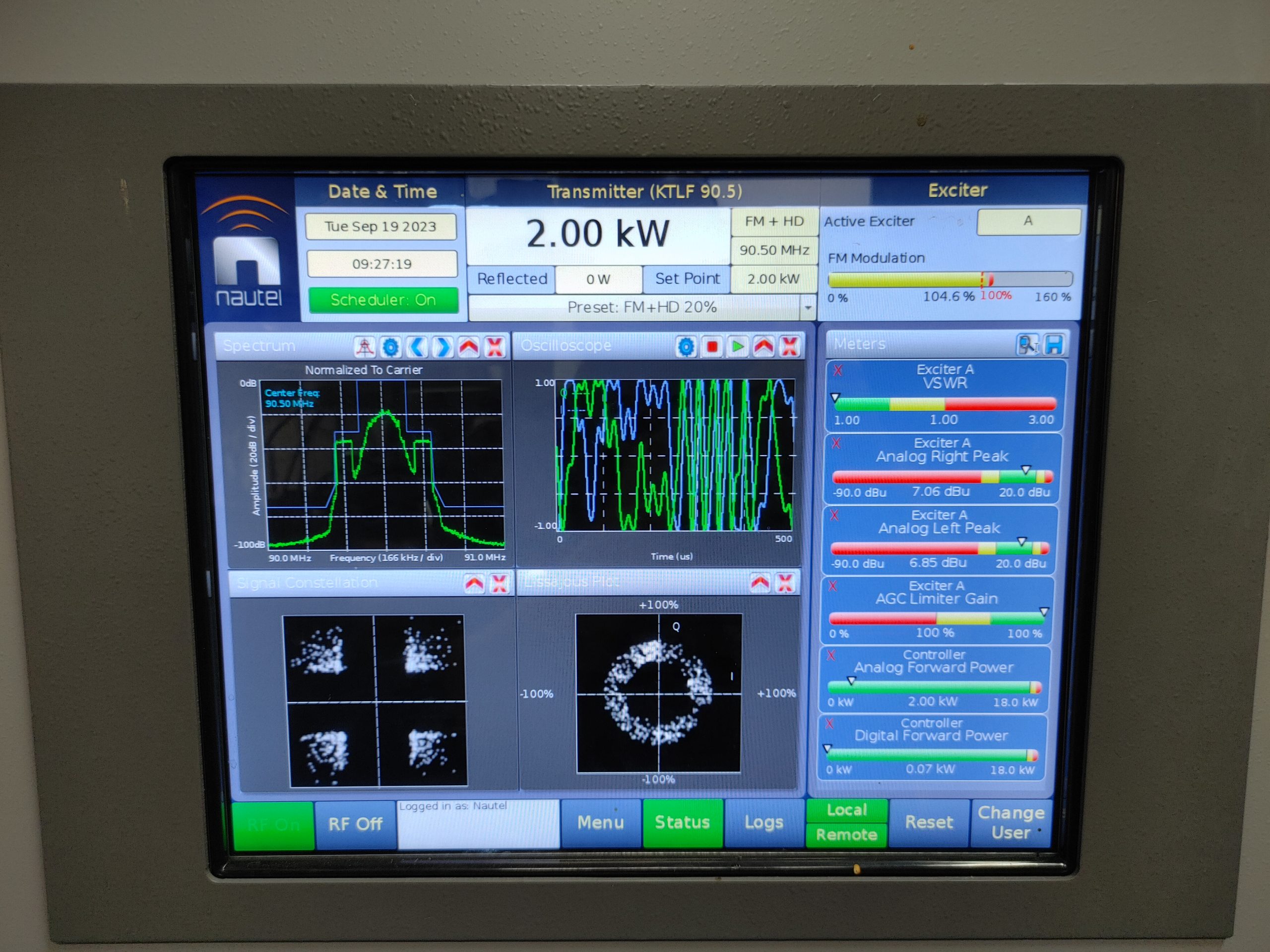
Most of these systems are adjusted to a shocking level of precision, because even 1% of reflected power amounts to hundreds of watts firing back into your transmitter. not good for stability or heat. So VSWR of less than 1.05 is common. Now imagine how much of a pain this becomes when you are combining multiple stations onto one antenna. This literally requires manual adjustment of the antennas and feedline for each frequency. Elaborate feed line matching circuits are made by climbers inserting inductive (ferrite) or capacitive (nylon) slugs into the transmission line at strategic points calculated by a computer. Of course, elements not modeled in the simulation require manual adjustment by going back-and-forth between transmitter and feeder to make adjustments to slug positions and sizes. This is also a multivariate process, so each adjustment made will affect matching for each channel. This job can take days.
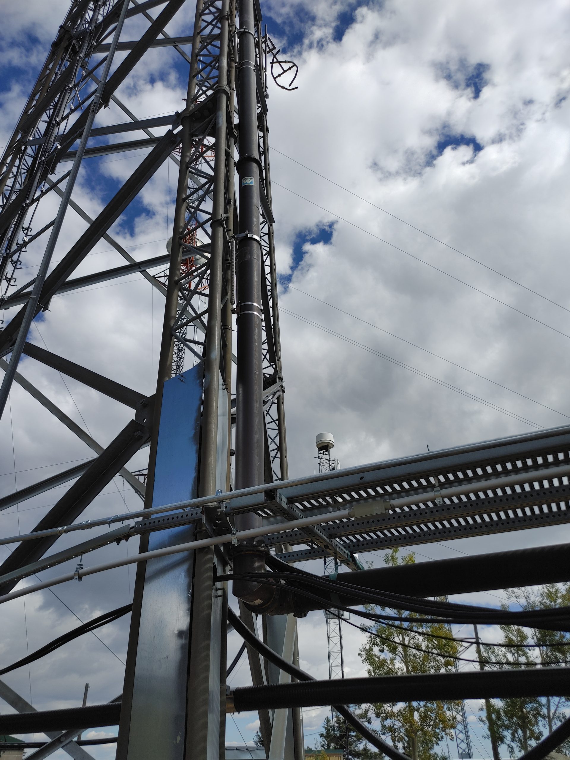
Above you will have seen some odd meanders of these massive feed lines. This is because apparently the out-of-band power reflected back into the transmitter by the cavity filters would cause some instability. This would manifest itself as inter-modulation distortion popping up outside of the station band. To solve this problem, extra feeder was installed to transform the impedance outside the passband to something the transmitters were happier with. This is very similar to the concept of the impedance inverter. See the following diagram of a smith chart to gain an understanding of how adding feedline length affects impedance. Essentially each quarter wavelength of transmission line will bring you half-way around the smith chart, “inverting” your impedance. Since the right edge represents open-circuit condition, and the left edge a short. Likely these transmitters were happier with something higher impedance rather than something potentially much like a short.

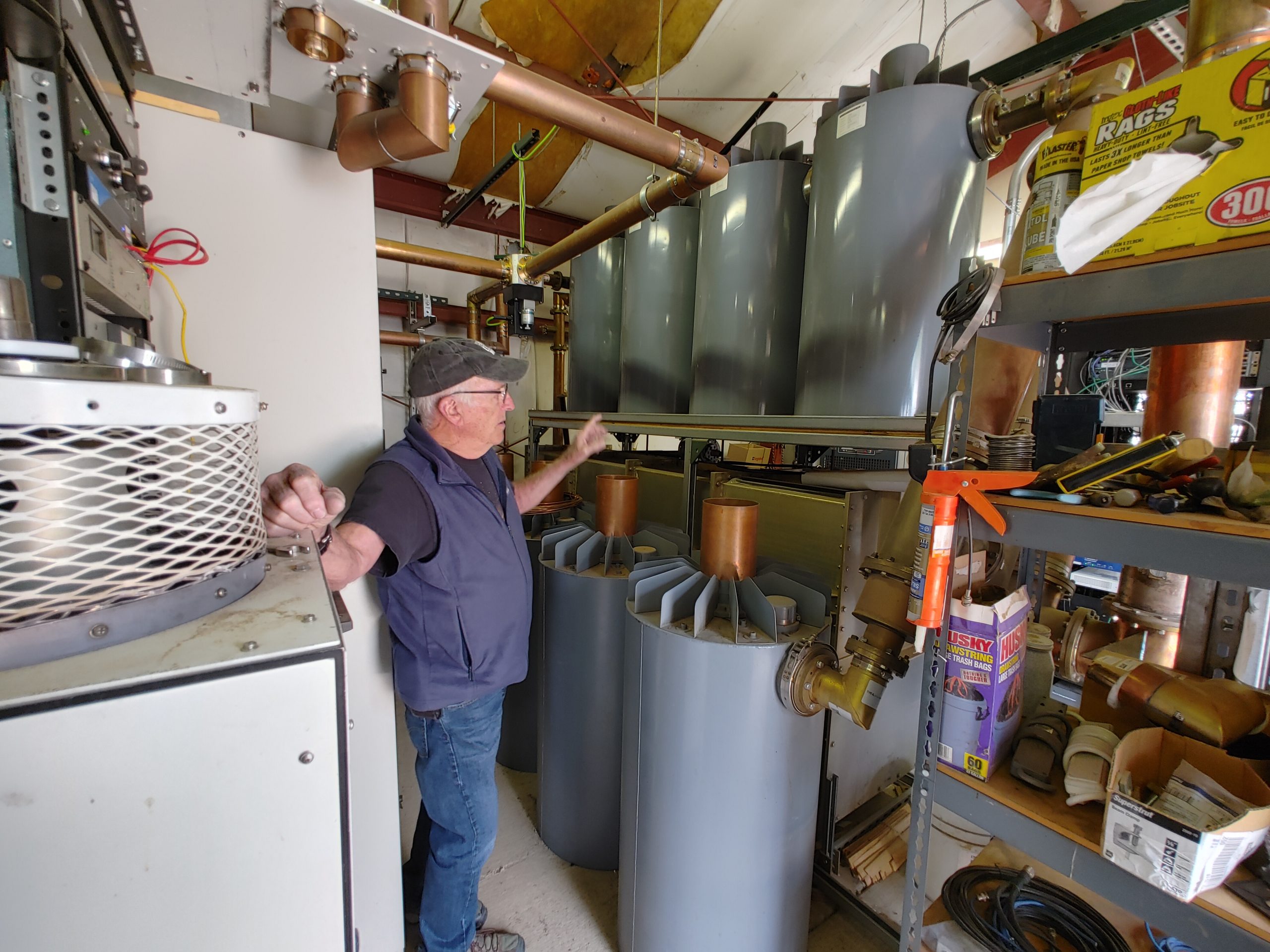
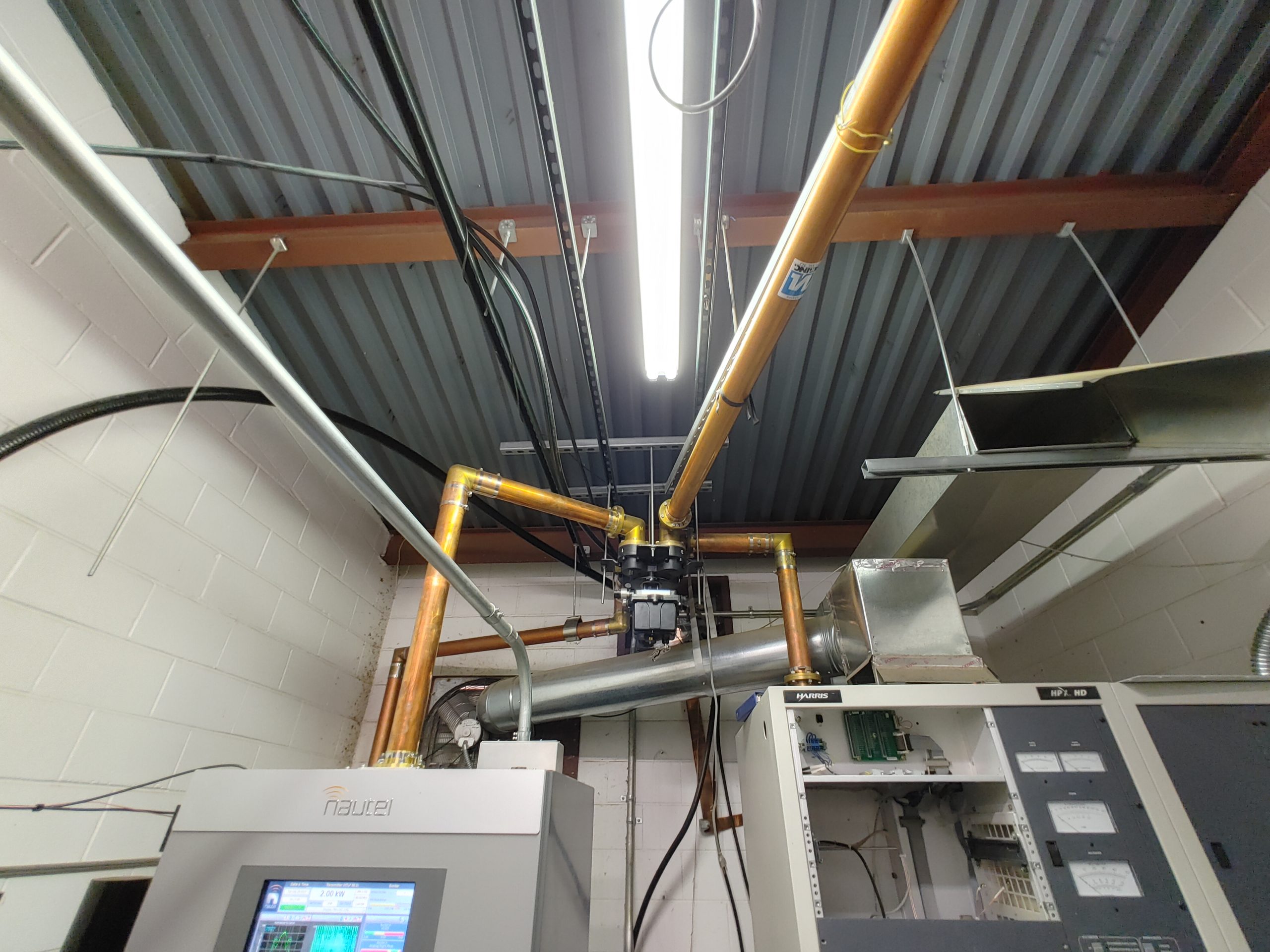
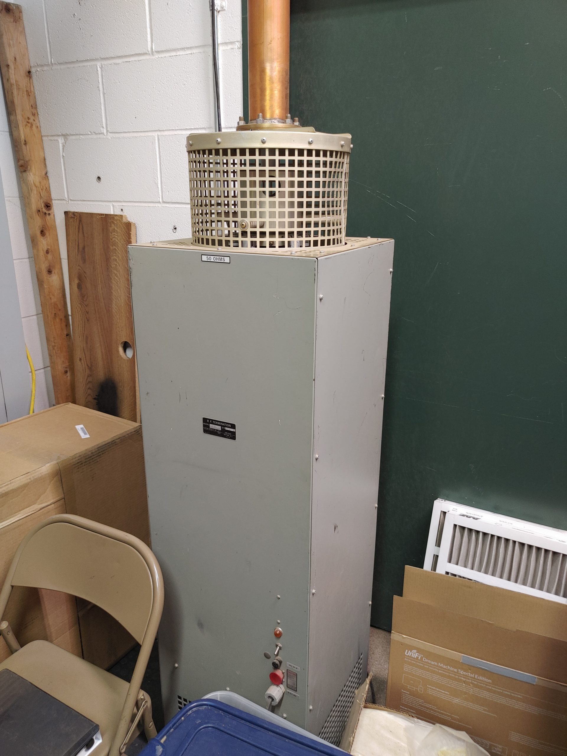
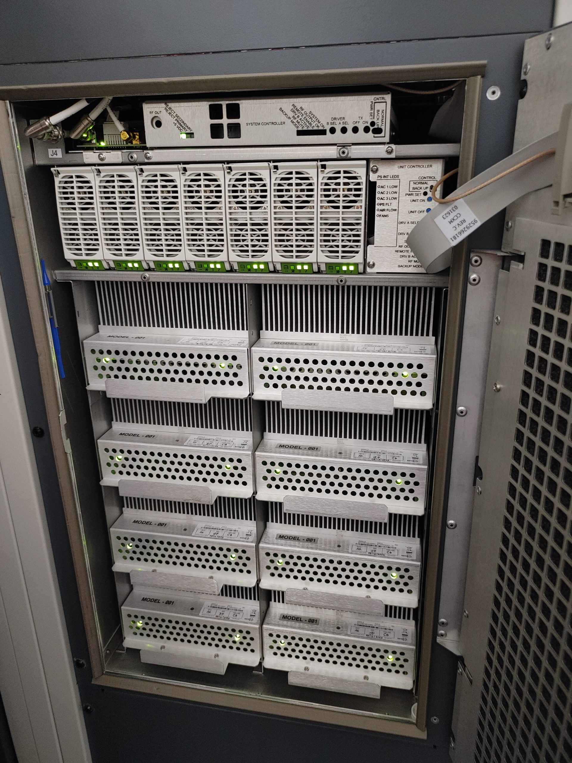
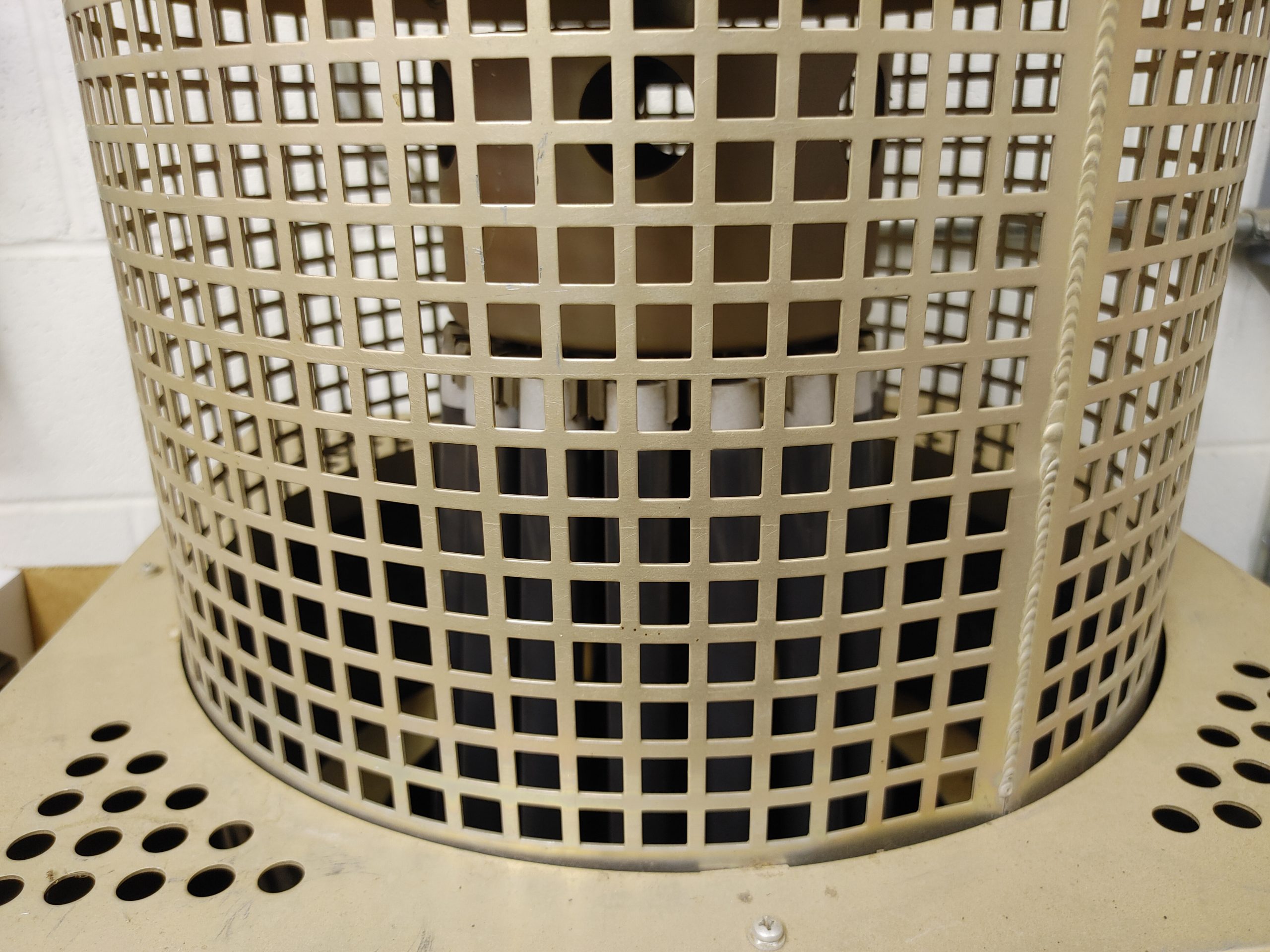
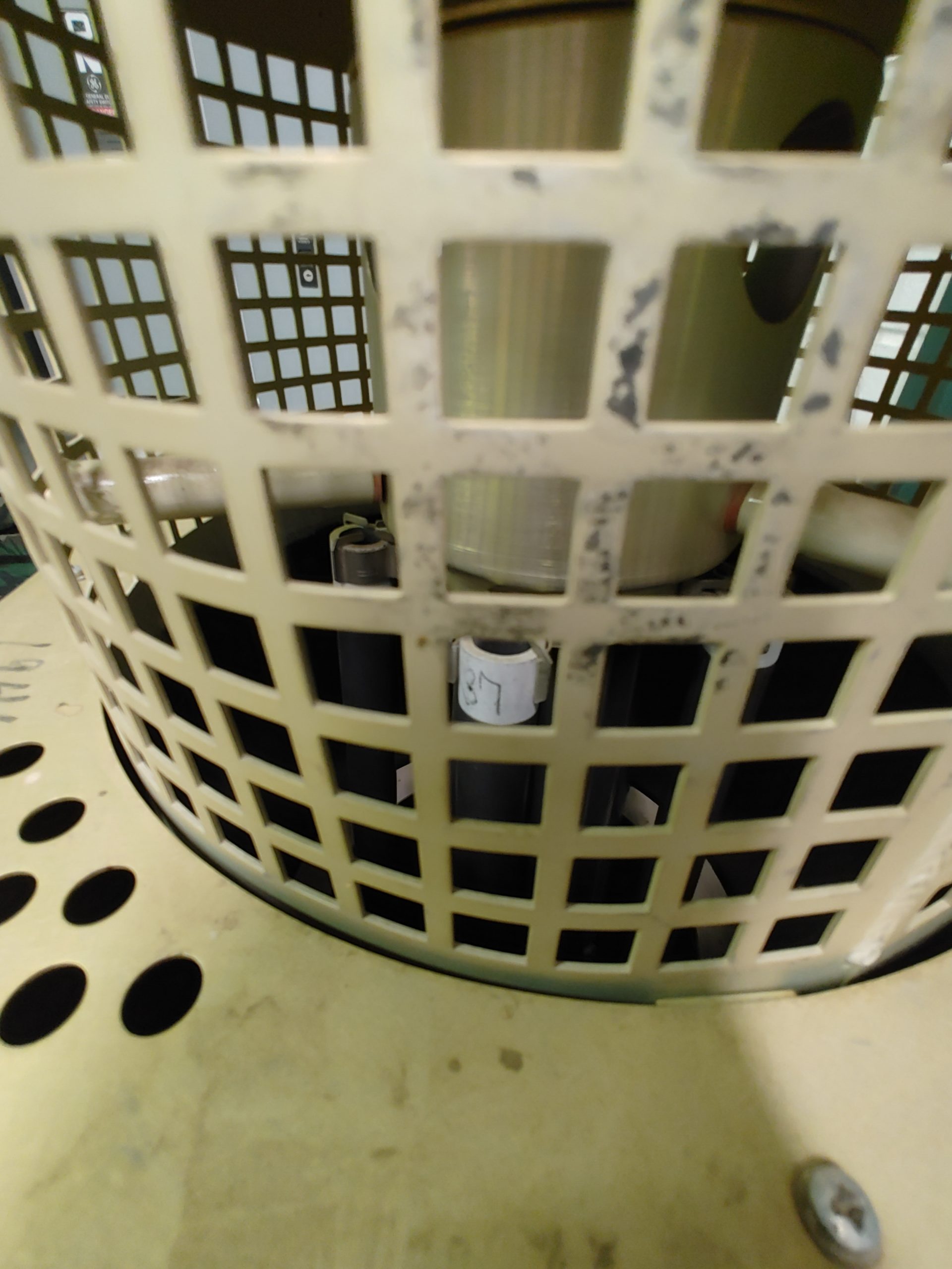
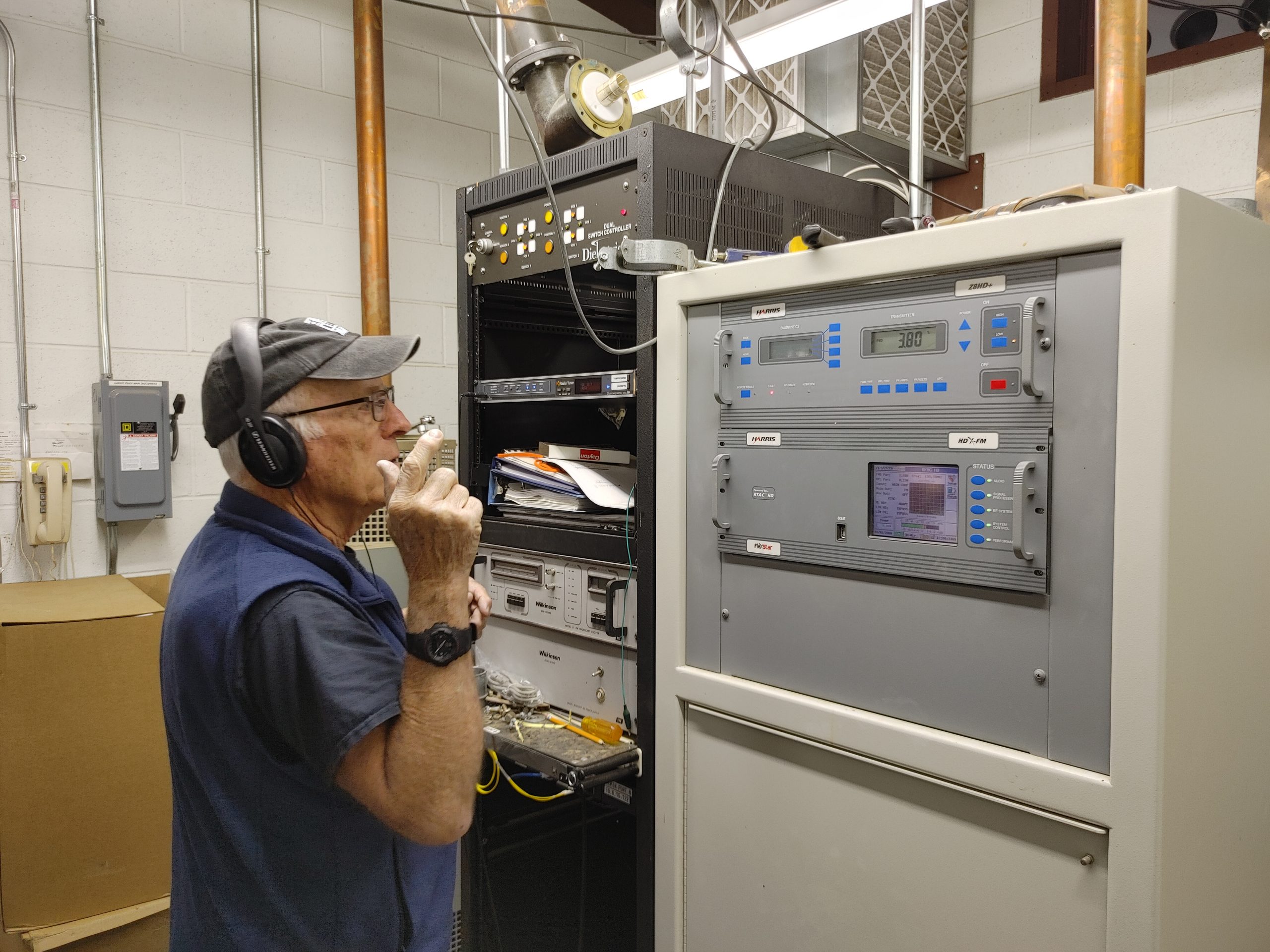
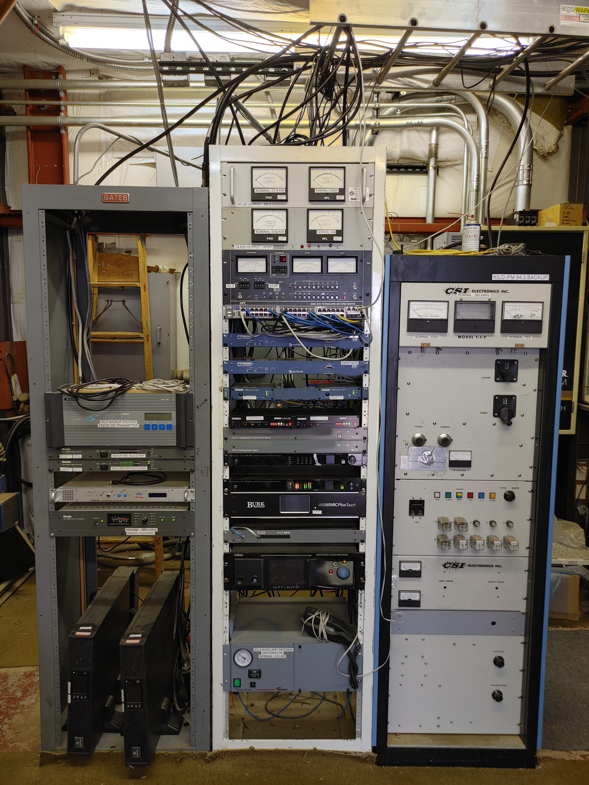
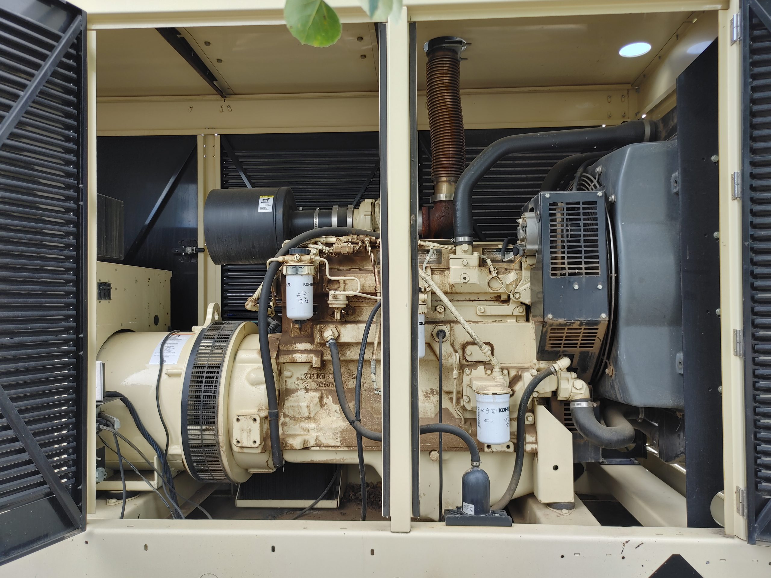
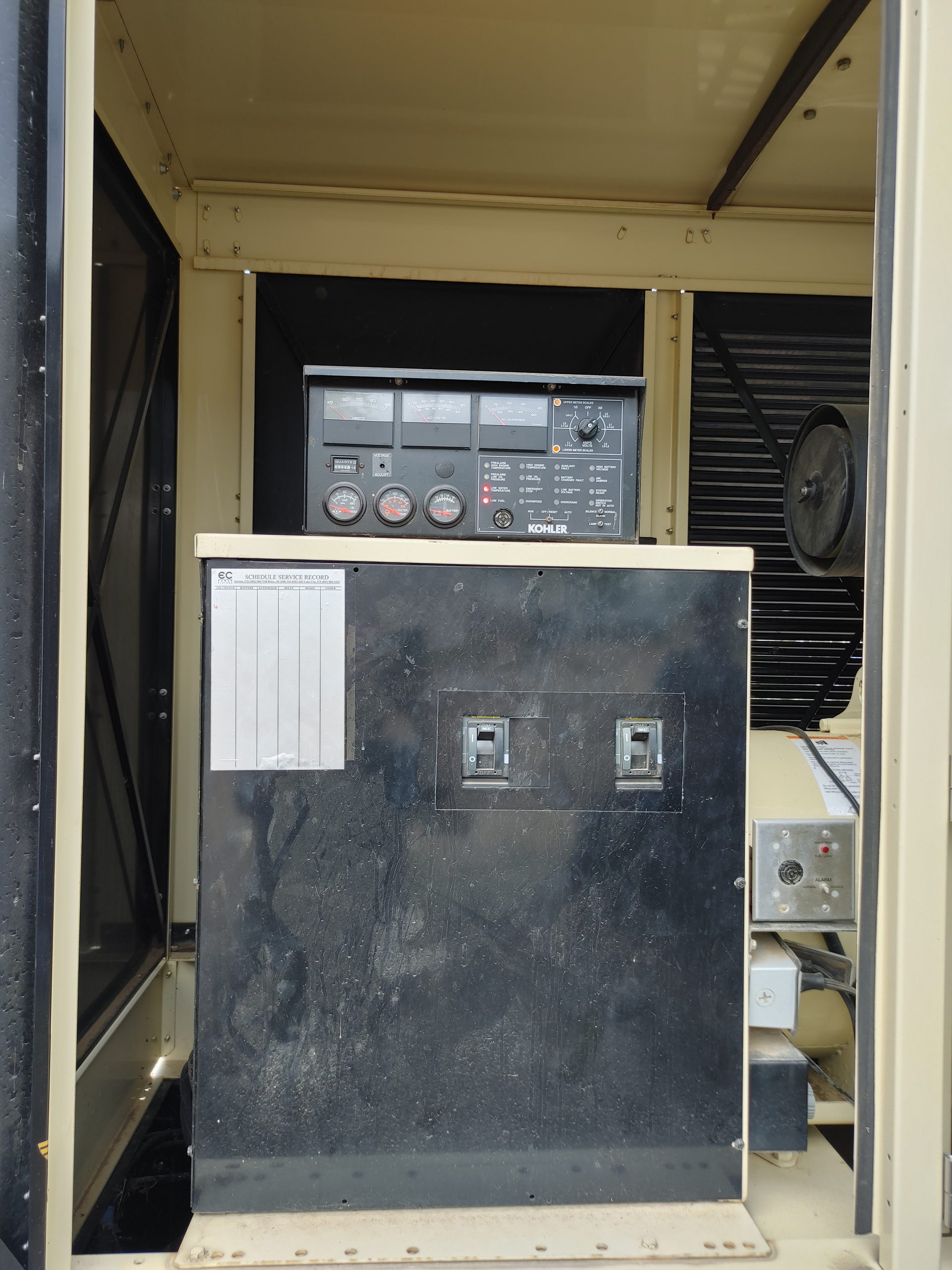
Now that we’ve seen the feed systems, we can take a look at the inside transmitter equipment. Most of everything is solid-state these days, though you will still find some tube-type backup amplifiers. These power amplifiers are made out of a large number of power supply and amplifier modules stacked in parallel allowing hot-swaps under partial failure conditions. These transmitters are even so sophisticated that they have web-portal monitoring and automatic remote diagnostics by the factory. Mostly, the chain for any given station consists of an STL receiver for the programming via microwave, this feeds an “exciter” modulating radio with an output of 10-100W. This is then fed into an HPA producing 25kW and carried outside by the piping. It’s common to see these accompanied by the BIGGEST 50 ohm dummy loads I’ve ever seen, some backup equipment, and monitoring gear or receivers. What’s quite interesting is many of these transmitters support HD (NRSC5) carriers and are largely linear to support this QPSK/OFDM waveform. Though the injection levels are usually on the order of -20dBc or -14dBc from the analog carrier, meaning the digital signal gets far less power. Part of the reason for this may be to reduce the PAPR requirement and thus linearity of the transmitter as some of these will intentionally and adaptively distort the transmit signal to reduce PAPR.


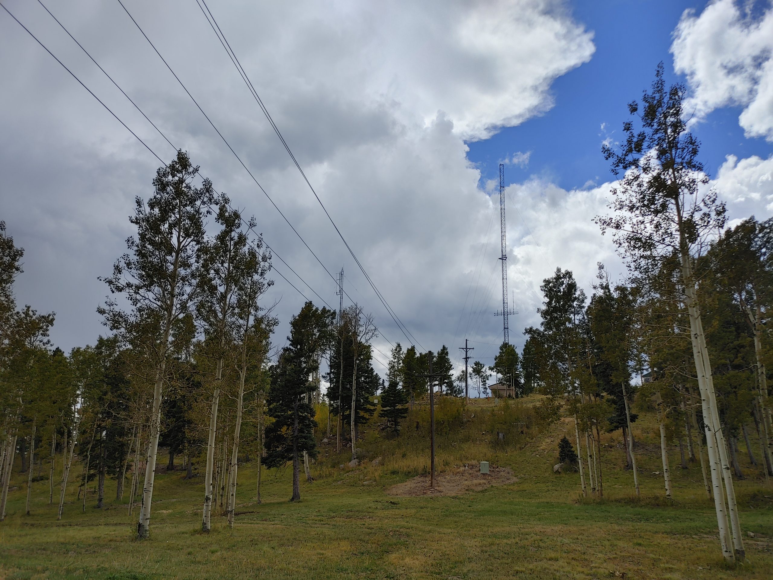
This was a “power-down” day where most of the transmitters were run at reduced power to allow a climber to inspect the integrity of a couple towers.
Here are some extra photos from the various installations around the complex. But since we’re already here, I may as well tell you a fascinating story about the one of the many bizarre issues one can expect to find in such an RF saturated environment. At one point, the military had a receiver monitoring the frequency 121.5MHz AM for some sort of air traffic. Now any sane person would tell you that a wide open AM detector on a mountaintop full of 25kW transmitters was an asinine idea, but this is the military, so intelligence is out the window. Predictably, they had a horrible interference issue, they couldn’t hear any of the signals they wanted. This prompted some calls and several companies were brought out to diagnose the issue. Unfortunately, these efforts were failing to identify the source. So here comes Ray with a brilliant idea. He takes a regular iCOM ham receiver which will allow tuning AM and FM on 121.5. He also brings a high selectivity cavity filter to place ahead of his receiver to make sure the rig isn’t producing any distortion of its own due to strong adjacent signals. He finds the interference is only LOUDER with the filtered rig. He then spends some time driving around the site hoping to find the source, only to see that it’s relatively uniform across the mountain. He then thinks, “wait a second, can we hear anything on this channel?” He turns the radio to FM and takes a listen. He hears a jumble of sound that actually seems like it could be one of the local broadcasts, even though they’re all supposed to be down below 107.9MHz. He however can’t quite make out what’s actually playing. Despite this, he passes the headset to his friend who runs programming for some of the local stations. He’s so familiar with the content that he almost immediately determines that this is indeed the audio for 90.3 and 105.9 on top of one another! How the hell is this possible? Well, hold on a second… the equation for closest 3rd order inter-modulation product on the high side is 2*f1-f2. This means 2*90.3-105.9 = 121.5MHz. OH SHIT. How is that happening? The output of all the transmitters on the site was checked, and they all have huge cavity filters anyway. Well then what’s going on? Well, let’s talk about inter-modulation for a second. IMD is a type of distortion caused by non-linearities in a passive or active conducting device.
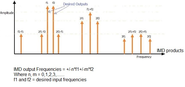
These normally undesirable effects typically occur in diodes and transistors. These effects are exploited by devices called mixers to up and down mix frequencies intentionally. However, this is not exclusive to intentional semi-conductor materials. This can occur in any media where the ratio of input and output are not perfectly linear. Meaning, this can happen when a semiconductor is formed by oxide layers touching a conductive surface, or materials of varying electrical properties coming into contact. So what conclusion does this leave? Well, this is a site full of such multi-material boundaries. Think of every single rusty bolt, joint, or cable winding… With this much input power, even the tiny amount of radiation these will produce is enough to overwhelm the signal of interest. So what was the solution? Move the receiver you dopes!
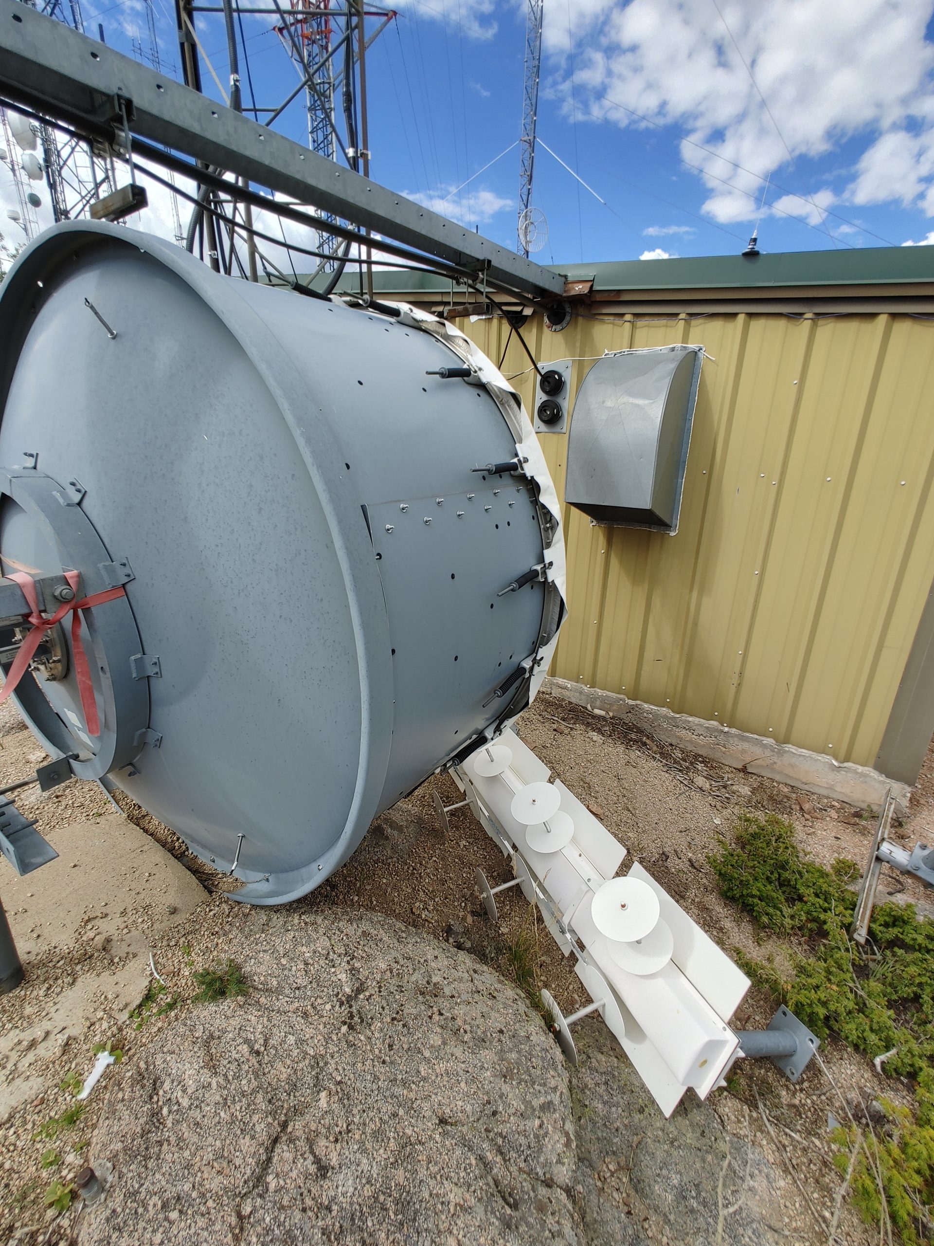


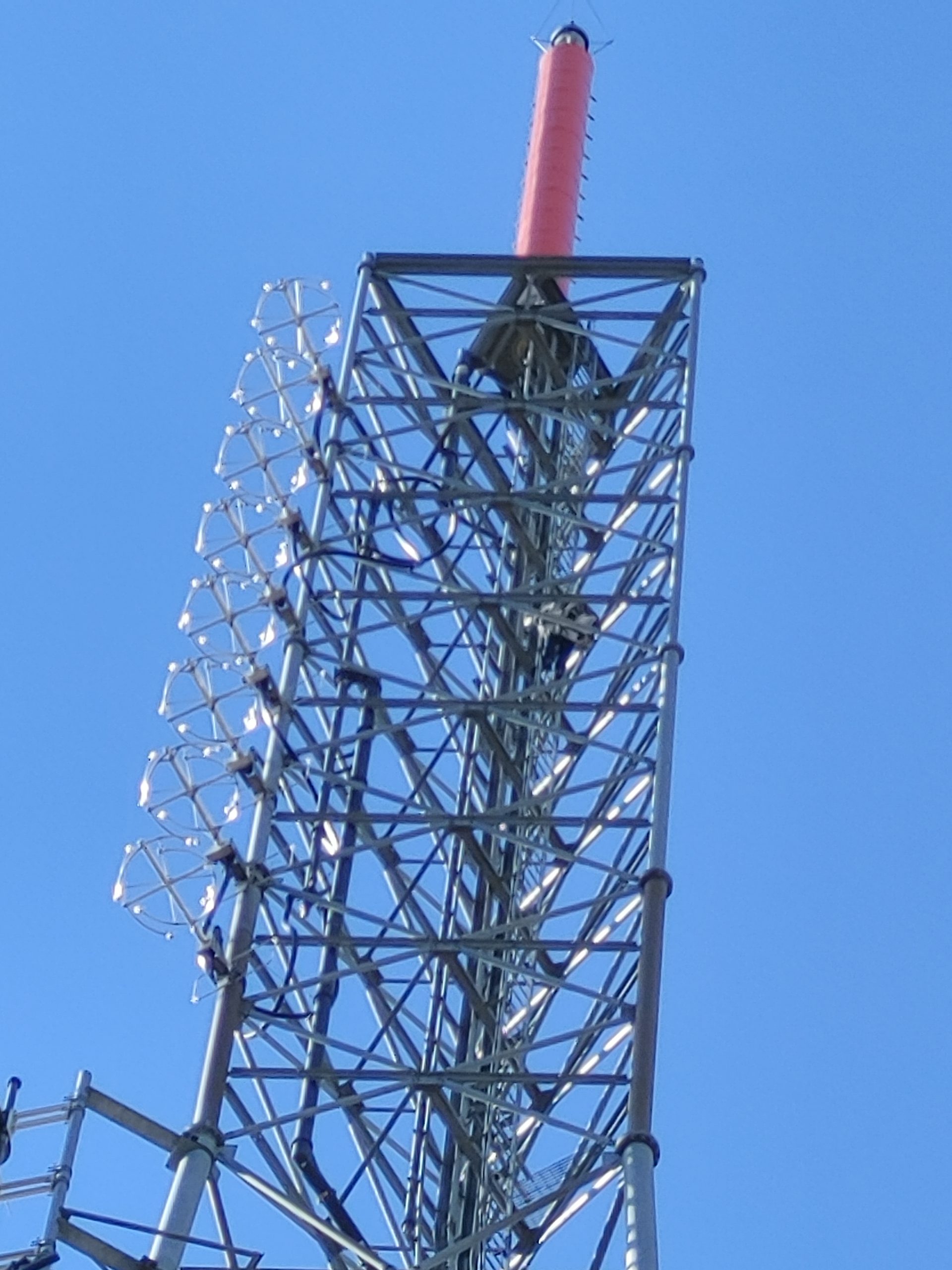
The above picture of the old antennas is interesting for a few reasons. Firstly, note the set of 4 curved dipoles per antenna. This antenna is designed to produce some sort of circular polarization which is common for FM. Also note the balls on the ends of each element. These are used to prevent corona discharge from the high standing voltages caused by high power input. These hollow steel tubes also house a wire for melting snow and ice to prevent excess load and impedance mismatching.
To touch on the need for L/RHCP. This is typical in the industry because it allows ambiguity in the receiver antenna orientation. i.e. We don’t know which way the listener has their antenna. cross-polarization loss of -20dB is typical, bad. Circular produces a loss of just -3dB for either linear polarization. It also allows some resistance to reflection fading since bounces will rotate the polarization of your signal depending on the angle of incidence. This obviously makes no difference for a CP signal.
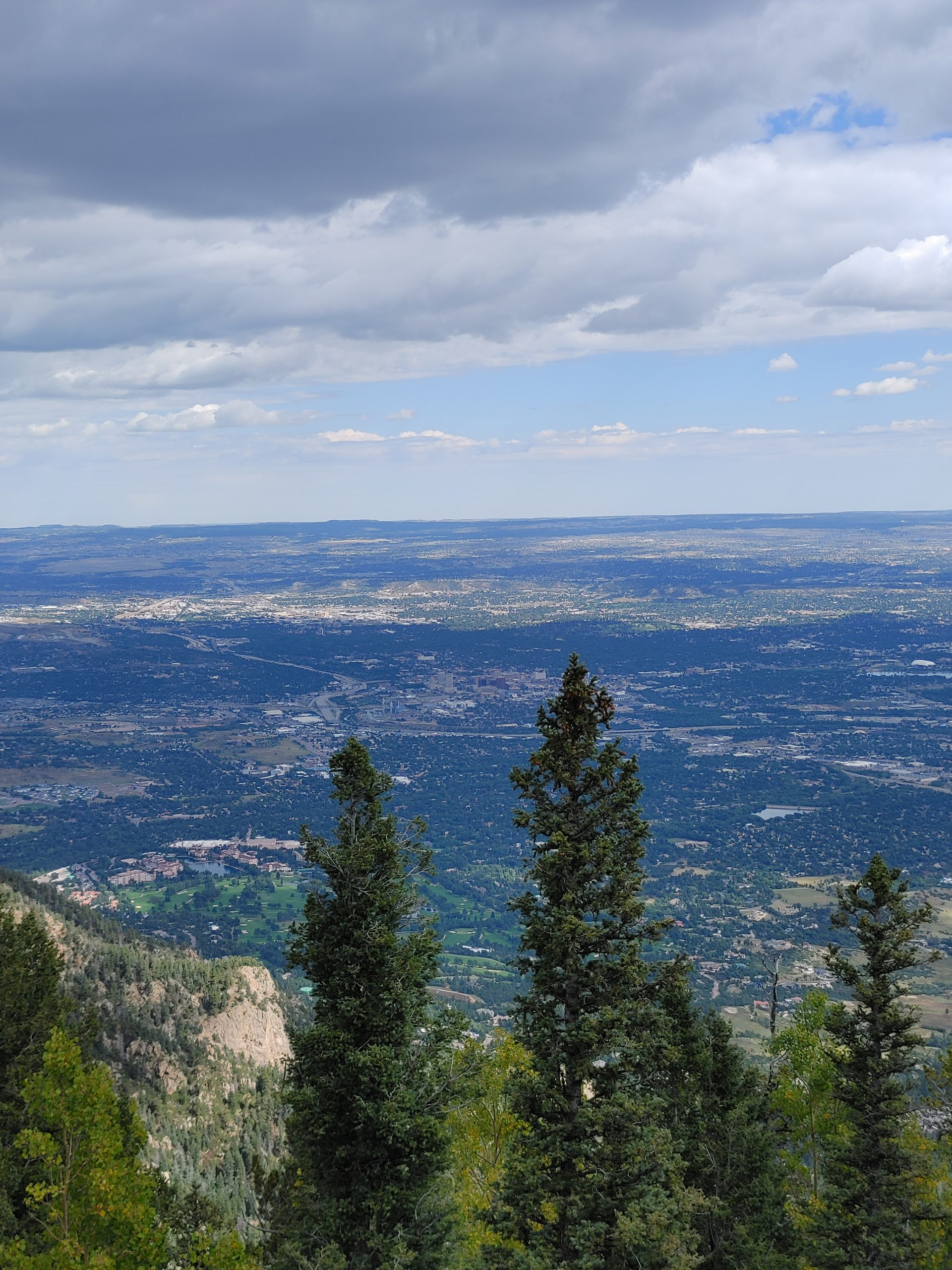
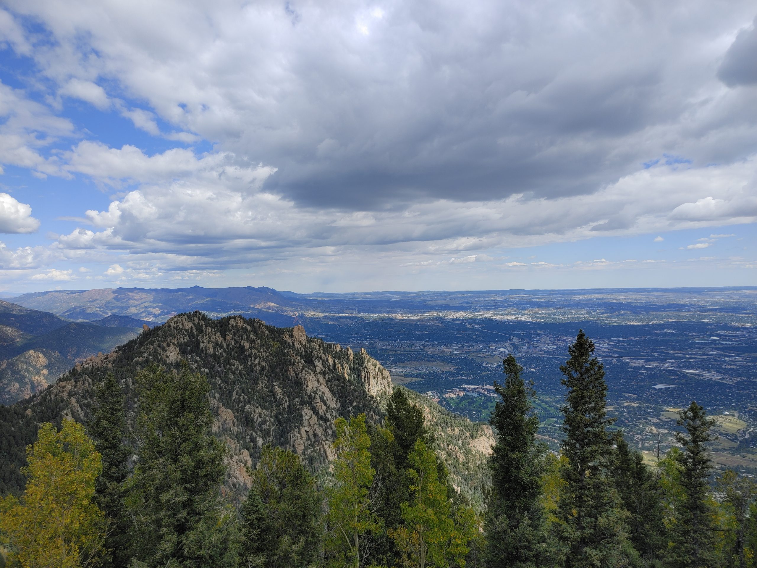
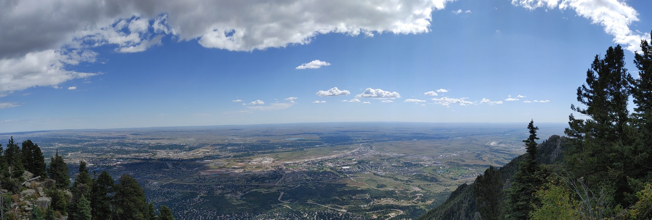
Here’s a few pictures of the amazing views from the top of the mountain! What a place to have a picnic! Though considering the exposure levels I might not advise loitering for too long outside… In recent years they elevated many of the antennas up the towers, but prior to this, there were signs littering the premises to not stay in particular locations for more than 75 seconds due to elevated field strengths. The signals here are strong enough to cause Comcast cable engineers servicing the neighborhoods downhill grief. Every small nick in the shield or poor connection causes the line to be swamped with broadcast signals.

Leave a Reply